FR4 is one of the most commonly used materials in the electronics industry, especially in the manufacturing of printed circuit boards (PCBs). As the backbone of most rigid circuit boards, FR4 not only offers excellent mechanical strength but also provides superior electrical insulation and good heat resistance. However, while many electrical engineers and PCB designers are familiar with FR4, they may not fully understand what it is, let alone why it is the most popular PCB substrate material.
In this article, we will explore the properties of FR4, why it holds a dominant position in the electronics industry, and how it compares to other materials in terms of PCB specifications. Additionally, we will discuss the performance of FR4 in various PCB applications, providing a deeper understanding of why this material is so widely used in circuit board design and manufacturing.
What is FR4 Material in PCBs?
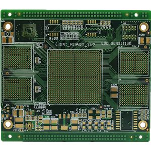
FR4, often written as FR-4, is both a name and a standard grade used in the manufacturing of printed circuit boards (PCBs). The term refers to a type of glass-fiber-reinforced epoxy laminate used as the primary substrate material in rigid circuit boards. It is also a material classification that signifies the quality and specific properties of the laminate. The “FR” in FR4 stands for “Flame Retardant,” while the “4” differentiates it from other similar materials, indicating its particular grade within a series of standards.
FR4 is a composite material with a fundamental structure comprising woven glass fibers that are formed into thin sheets. These glass fibers provide the necessary structural integrity to the laminate. The core layer of glass fiber is then impregnated with a flame-retardant epoxy resin, which not only gives the material its rigidity but also contributes to its excellent electrical properties and high dielectric strength.
This unique combination of materials makes FR4 a versatile and cost-effective substrate for PCBs, highly favored by electrical engineers and PCB designers. The resin provides durability, thermal stability, and electrical insulation, while the glass fiber contributes to the strength and lightweight nature of the material.
Why FR4 is Widely Used in PCB Manufacturing
The popularity of FR4 as a PCB base material can be attributed to its array of beneficial physical and electrical properties:
- High Dielectric Strength: FR4 offers excellent electrical insulation, making it ideal for high-voltage and high-frequency applications.
- Lightweight and Strong: With a high strength-to-weight ratio, FR4 ensures durability without adding unnecessary bulk, crucial for compact and portable electronic devices.
- Moisture Resistance: The material’s resistance to moisture ensures the stability and reliability of PCBs, even in humid or damp environments.
- Thermal Stability: FR4 exhibits a relatively high heat tolerance, making it suitable for use in a wide range of temperatures without compromising performance.
- Cost-Effective: Compared to other PCB materials, FR4 is affordable, which helps keep manufacturing costs lower without sacrificing quality.
These properties combine to make FR4 the go-to choice for most PCB applications, from consumer electronics to industrial systems, automotive electronics, and more. In addition to its inherent characteristics, FR4 is also easy to work with in PCB fabrication processes, offering great flexibility for complex designs and multi-layer circuits. Whether for single-sided, double-sided, or multi-layer PCBs, FR4 remains a dependable and popular material in the industry.
How FR4 is Used in PCBs
The unique properties of FR4 make it the material of choice for high-quality PCB manufacturing. When used appropriately, FR4 serves as the foundation for creating cost-effective yet reliable circuit boards, offering a balance of performance and affordability.
In a PCB, FR4 acts as the primary insulating skeleton, providing structural support for the circuit. It serves as the substrate to which electrical components and conductive pathways are attached. Once the FR4 board is prepared, it is bonded to one or more layers of copper foil using heat and adhesive. The copper layers form the conductive paths that make up the PCB’s circuitry. Depending on the design requirements, these copper layers may be applied to one or both sides of the FR4 substrate.
Layered and Multi-Layer PCBs
For more complex designs, FR4 is often used in multi-layer or multi-sided configurations. In these advanced PCBs, additional layers of FR4 and copper may be stacked together to accommodate intricate circuit layouts and to meet the space and performance requirements of modern electronic devices.
Once the copper is applied to the FR4 base, the next step is to create the circuit traces. This is typically achieved through a process of photolithography and etching, which defines the precise routing for electrical signals. After the traces are etched, a solder mask layer is applied to protect the copper and prevent unintentional short circuits. The solder mask also ensures proper placement of components during the final assembly phase.
Preparation for Assembly
The next steps in PCB manufacturing involve adding silk screen layers for labeling component placements, followed by the soldering process. These processes ensure that the circuit board is ready to receive the components and be assembled into a fully functional product. FR4’s robust properties—its electrical insulation, mechanical stability, and moisture resistance—ensure that the board performs reliably throughout the life cycle of the device.
In summary, FR4 is an integral component in PCB production, providing the necessary base material that supports both electrical and mechanical integrity. From single-layer to multi-layer, FR4 enables the creation of diverse and intricate circuit designs that are critical to the performance of modern electronic products.
How to Determine the FR4 Thickness for PCB Design
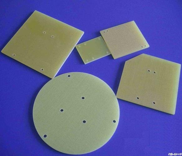
When selecting laminates for a PCB project, designers or electrical engineers must specify the FR4 thickness. This thickness is typically measured in thousandths of an inch or millimeters, depending on the unit standards and design preferences. The thickness of FR4 boards can vary widely, typically ranging from fractions of a mil to several inches, based on the requirements of the specific project. While PCB thickness may seem like a minor factor, it is, in fact, crucial to the performance and functionality of the circuit board. Below are the key factors that influence the selection of FR4 thickness for a PCB:
1. Space Constraints: Thinner is Better
For designs with limited space, such as compact electronic devices like USB connectors or Bluetooth accessories, opting for a thinner FR4 board is often the preferred choice. In many cases, thinner PCBs allow for more efficient use of space, enabling a more compact device design. Even for larger projects, thinner FR4 PCBs are often preferred to save space within the device.
2. Connector Considerations: Incorrect Connections Can Cause Damage
In a double-sided PCB design, edge connectors must fit precisely with the PCB thickness. If the board is too thick, the connectors may not engage properly, leading to poor connections or potential damage. Selecting the correct FR4 thickness ensures that edge connectors are properly aligned and securely connected to the PCB, avoiding any connection-related issues that could impact the functionality or reliability of the design.
3. Impedance Matching: Essential for Circuit Stability
The thickness of the FR4 layer directly impacts the capacitance and, therefore, the impedance characteristics of the PCB. This is particularly crucial in high-frequency applications, such as RF (radio frequency) and microwave circuit designs, where impedance matching is essential for signal integrity and optimal circuit performance. The thickness of FR4 determines the dielectric layer’s thickness, which in turn affects capacitance values and ensures proper impedance matching for high-frequency signal transmission.
4. Flexibility Requirements: Depends on the Application
Thinner FR4 boards typically offer some degree of flexibility, which can be beneficial in certain applications, especially when the PCB is subject to bending or mechanical stress. For example, flexible PCBs are commonly used in automotive or medical applications where the board needs to flex or withstand constant movement. However, too much flexibility can negatively impact the PCB manufacturing process, particularly during soldering and assembly. Excessively flexible boards may warp during soldering, resulting in components being placed at incorrect angles or damaging newly placed components and connections.
5. Design Requirements: Application-Specific Considerations
Thin FR4 boards are not always the best option, primarily due to their limitations in handling complex machining or larger mechanical loads. Thin boards may not support deeper grooves or withstand significant pressure, whereas thicker boards are more suitable for these requirements. When selecting the optimal FR4 thickness, designers must carefully evaluate the application’s specific needs, ensuring that the board’s thickness complements the intended use.
6. Component Compatibility: Influences Component Mounting
The thickness of the PCB also affects how components fit and are mounted on the board. Like edge connectors, many components are designed to fit within a specific range of PCB thicknesses, especially through-hole components. If the FR4 board is too thin or too thick, it may be incompatible with certain components, which could create assembly challenges or require additional modifications.
7. Weight: Lightweight Products Are More Attractive
The thickness of the FR4 board directly influences the final weight of the PCB. While weight may not be a concern for all applications, it is often a critical factor in consumer electronics, where lighter products are more desirable. A thinner FR4 PCB can reduce the overall weight of the device, lowering transportation costs and making the product more appealing to consumers. Lighter designs may also enhance the product’s portability and usability.
Selecting the appropriate FR4 thickness is a vital decision in PCB design. It requires a careful balance of factors such as space constraints, connection requirements, electrical performance, flexibility, and compatibility with components. Designers must ensure that the chosen thickness meets the functional needs of the PCB while also considering manufacturing feasibility and cost-effectiveness. By properly selecting the thickness of the FR4 material, a PCB can maintain optimal performance, reliability, and manufacturability across its intended application.
When to Use FR4 for PCB Design
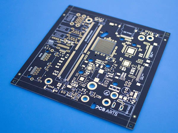
FR4, an epoxy-based laminate, is one of the most commonly used materials in PCB fabrication due to its cost-effectiveness, mechanical strength, and reliable performance. It is considered the go-to material for many electronic applications, especially where budget constraints are a concern. However, while FR4 is highly versatile, it is not suitable for every application, particularly those involving high-frequency designs. In such cases, specialized high-frequency laminates are often preferred.
Choosing between FR4 and high-frequency laminates can be a challenging decision, as it depends on a variety of factors such as material properties, the performance requirements of the final product, and cost considerations. Below is a detailed guide on how to make an informed choice when deciding between FR4 and high-frequency laminates for PCB construction.
Key Considerations in Material Selection
1. Cost: FR4 Is More Budget-Friendly
The primary advantage of using FR4 is its affordability. As one of the most common PCB substrates, FR4 is widely available and significantly less expensive than high-frequency laminates. This makes FR4 the default choice for many cost-conscious designers and manufacturers. On the other hand, high-frequency laminates come with a higher price tag, which can be a significant limiting factor when budget constraints are a key concern.
2. Signal Loss: Lower Df Minimizes Loss
Signal loss is a critical consideration in PCB design, especially in high-frequency applications where signal integrity is paramount. FR4, while suitable for many applications, is not ideal for low signal loss in high-frequency designs. This is because FR4 has a higher dissipation factor (Df) than high-frequency laminates. The Df of FR4 is approximately 0.020, while most high-frequency laminates have a Df around 0.004, which is approximately five times lower.
A lower Df results in reduced signal loss, which is particularly important in high-frequency circuits where maintaining signal quality is crucial. Additionally, the Df of FR4 increases with frequency, meaning that at higher frequencies, signal loss becomes even more significant. High-frequency laminates, with their more stable Df characteristics, exhibit less signal loss at elevated frequencies, making them more suitable for RF and microwave applications.
3. Impedance Stability: Dk Consistency Is Crucial
For many designs, especially in high-frequency circuits, maintaining consistent impedance across the PCB is critical. Impedance stability is closely linked to the material’s dielectric constant (Dk), which should remain stable across temperature variations to ensure predictable circuit performance.
FR4 is less reliable in this regard, as its Dk can vary significantly both within a single PCB and with changes in temperature. This can lead to unpredictable impedance, affecting signal integrity. In contrast, high-frequency laminates offer greater Dk stability, ensuring that impedance remains consistent across the board and throughout temperature changes, which is particularly important in high-frequency designs where signal integrity is essential.
4. Temperature Management: High-Frequency Laminates Outperform FR4
Temperature performance is another key consideration when selecting materials for PCB fabrication. The coefficient of thermal expansion (CTE) of a material affects its ability to maintain consistent electrical properties under varying thermal conditions. This is especially important in designs that will operate in high-temperature environments.
The dielectric constant’s thermal coefficient provides a useful metric for comparing materials. For FR4, this coefficient is about 200 parts per million per degree Celsius, while high-frequency laminates have a significantly lower thermal coefficient of approximately 40 parts per million per degree Celsius. This means that FR4’s dielectric constant will change more with temperature fluctuations, leading to greater potential for impedance instability in thermal cycling. High-frequency laminates, with their lower thermal coefficients, maintain more stable properties across temperature changes, making them ideal for environments with significant thermal variation.
5. Dielectric Constant (Dk): Selecting the Optimal Value
The dielectric constant (Dk) of a material influences the design of transmission lines and affects the overall size of the PCB, particularly in high-frequency circuits like RF or microwave designs. A higher Dk value allows for smaller transmission lines, which in turn results in a more compact PCB.
FR4 has a Dk of around 4.5, which is lower than that of high-frequency laminates, which typically range from 6.15 to 11. By using high-Dk materials, it is possible to significantly reduce the size of the PCB—often by as much as 25% or more. This reduction in size can be crucial for high-frequency designs, where compactness is often a critical factor.
6. Operating Environment: Considerations for Harsh Conditions
When deciding between FR4 and high-frequency laminates, the operating environment is another important factor to consider. The PCB’s performance can be significantly affected by environmental conditions, such as humidity, temperature, and exposure to chemicals. High-frequency laminates generally offer better moisture resistance and thermal stability compared to FR4.
For applications in extreme environments—such as outdoor, industrial, or military conditions—high-frequency laminates provide superior performance in maintaining functionality under harsh conditions. In these cases, high-frequency laminates’ higher resistance to moisture absorption and thermal stress may make them the better choice.
Making the Right Choice: FR4 vs. High-Frequency Laminates
After reviewing the considerations listed above, how does an electrical engineer or PCB designer make the right decision between FR4 and high-frequency laminates? First, it’s essential to evaluate and compare the electrical and mechanical requirements of the final PCB using precise parameters. Then, designers should assess how well FR4 meets those requirements compared to high-frequency laminates, particularly in applications involving high-frequency signals.
Industry datasheets are a useful resource for obtaining more precise values for each of the factors discussed. In most cases, FR4 remains a reliable and cost-effective option for many standard electronic applications, offering a good balance of mechanical strength, electrical stability, and low cost. However, for specialized applications—particularly those involving RF, microwave, or high-speed digital circuits—high-frequency laminates provide the necessary performance characteristics to ensure reliable operation at high frequencies.
While FR4 is a widely used material due to its low cost, mechanical stability, and sufficient electrical performance for many applications, it is not always the best choice, especially in high-frequency designs. High-frequency laminates, with their superior signal integrity, impedance stability, and temperature management, are more suited to advanced RF and microwave circuits. However, for most general-purpose PCBs, especially when cost is a primary concern, FR4 remains the go-to material. The decision between FR4 and high-frequency laminates ultimately depends on the specific requirements of the project, where performance needs outweighing cost considerations justify the use of higher-end materials.
Contact CustomPCBA for Tailored PCB Solutions
If you’re in need of high-quality FR4 PCBs or circuit boards made from other materials, CustomPCBA is here to meet your specific requirements. We specialize in providing custom PCB solutions tailored to your exact needs, ensuring high performance and reliability across a wide range of applications. With a focus on superior quality, on-time delivery, and precision engineering, CustomPCBA stands as your trusted partner for all PCB fabrication needs.
Since our inception in 2005, CustomPCBA has been committed to delivering exceptional products that meet the highest international standards. Based in Harrisburg, Pennsylvania, our team brings decades of experience in PCB manufacturing, offering not only a wide array of circuit board materials but also dedicated engineering support to guide you through the design and manufacturing process.
In addition to providing premium-quality PCBs, we offer competitive pricing structures to ensure that you get the best value for your investment. Whether you need a single prototype or large-volume production, CustomPCBA is equipped to handle projects of any scale with the utmost attention to detail and precision.
Why Choose CustomPCBA?
- Wide Range of Materials: We offer FR4, high-frequency laminates, and other specialized PCB materials to suit your specific needs.
- Precision Engineering: Our team provides expert engineering support to optimize your design for performance and manufacturability.
- Quality Assurance: We adhere to strict quality control standards, ensuring that every PCB meets the highest international benchmarks.
- Timely Delivery: We pride ourselves on on-time delivery, helping you meet tight project deadlines.
- Competitive Pricing: CustomPCBA offers cost-effective solutions without compromising on quality.
For further inquiries or to discuss your PCB requirements, please contact us today. Our team is ready to assist you with tailored solutions and the expertise to ensure your project’s success.

