Understanding PCB Components for Effective Repair
In PCB repair, a comprehensive understanding of the components that make up the circuit board is essential for troubleshooting and effective fixes. Common components such as resistors, capacitors, transistors, and integrated circuits (ICs) each serve specific functions within the circuit. A failure in any of these components can lead to circuit malfunctions, and recognizing when one of these components is faulty can help you pinpoint the issue more accurately.
Example: During a visual inspection, you might notice a swollen capacitor. This is a clear indication of capacitor failure, and knowing the role of the capacitor in the circuit helps you diagnose the problem. Capacitors store and release electrical energy; a malfunctioning capacitor can lead to power instability or signal interference, making it critical to replace the faulty component.
Identifying Common PCB Issues
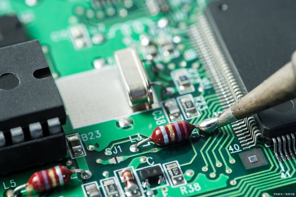
Effective troubleshooting begins with recognizing common PCB faults. Some of the most frequent issues include shorts, broken traces or pads, component failures, and power-related issues. A variety of diagnostic tools and methods, including multimeters and oscilloscopes, are used to identify the root cause of these faults.
Example: Suppose you're troubleshooting a PCB and there is no output sound. Using an oscilloscope, you can measure the output signals at various points within the audio circuit. This will help you locate where the signal is either missing or distorted, allowing you to focus your repairs on the exact failure point.
Essential Tools and Equipment for PCB Repair
The right tools are indispensable for successfully repairing a PCB. The essential toolkit typically includes a soldering iron, desoldering tools, a multimeter, an oscilloscope, and a soldering station. Selecting the appropriate tools based on the complexity of the repair task is crucial for precision and efficiency.
Example: When removing components, a desoldering pump or desoldering braid can be used to remove excess solder. For precise and reliable soldering, an adjustable temperature-controlled soldering iron ensures that the components are soldered with the correct heat without damaging sensitive parts. Using high-quality tools will improve the overall quality and speed of the repair process.
Step-by-Step PCB Repair Process
A systematic and methodical approach is crucial for successful PCB repair. The following steps outline the key stages of the repair process: safely removing faulty components, cleaning the PCB, replacing damaged components, and repairing broken traces or pads. By following these steps, you can ensure a thorough and effective repair.
1. Component Removal and PCB Cleaning
The first step in PCB repair is to remove any faulty components. Careful removal is essential to avoid causing further damage to the PCB or other components. Once the faulty components are removed, clean the PCB using appropriate methods, such as isopropyl alcohol and a soft brush, to remove solder flux, dust, and other contaminants. Cleaning helps prevent future issues and ensures that the new components will adhere properly.
Example: Suppose you've identified a defective resistor. The step-by-step process includes desoldering the faulty resistor using a soldering iron and desoldering pump or braid, cleaning the solder pads with isopropyl alcohol, selecting a replacement resistor that matches the original specifications, and then preparing the pads for soldering.
2. Component Replacement and Soldering
Once the PCB is clean, the next step is to install the replacement components. The new component must be carefully soldered to the PCB to ensure a strong, reliable connection. The soldering process involves applying flux, placing the component, and using the appropriate technique to heat the component and the pad simultaneously. Proper soldering ensures that the component is securely attached and that the electrical connection is stable.
Example: After selecting a replacement surface-mount resistor, use a precision soldering iron to apply flux to the pad and component leads. Place the component in the correct orientation, then heat it with the soldering iron to create a clean, solid joint. Ensure that there are no cold solder joints or bridges.
Advanced PCB Soldering Techniques
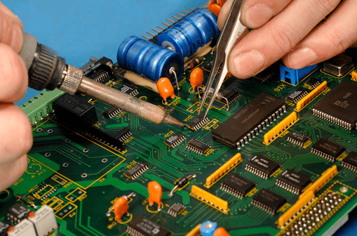
Mastering soldering techniques is critical in PCB repair, especially for complex repairs. Proper soldering ensures that the electrical connections are stable, reducing the risk of future failures. Different soldering methods are required depending on the type of component and the PCB design.
1. Through-Hole Soldering
Through-hole components require soldering from both sides of the board. Proper heat management is crucial to ensure that the solder flows evenly and does not damage the PCB or components. Make sure the soldering iron is at the right temperature and apply enough solder to form a solid joint.
2. Surface-Mount Technology (SMT) Soldering
SMT components are mounted directly on the surface of the PCB. These components are typically smaller and require precise handling. Techniques such as hot air reflow and solder paste application are used to solder SMT components. Hot air rework stations are often employed to heat the component and PCB simultaneously to ensure an even and accurate solder joint.
3. Reflow Soldering
For high-volume production and complex designs, reflow soldering is used. This technique involves applying solder paste to the PCB pads, placing the SMT components, and then using a reflow oven to heat the entire board. The paste melts, creating reliable solder joints between the component leads and PCB pads.
Example: To replace a surface-mount component, apply solder paste to the pads, position the component, and use a hot air rework station or reflow oven to heat the board. The solder paste will melt, creating the perfect solder joints for the new component.
Preventive Measures and Safety Protocols
PCB repair involves handling sensitive electronic components and potentially hazardous materials. Implementing proper safety measures and following best practices for static discharge, ventilation, and handling are crucial to ensure both personal safety and the integrity of the components.
1. Electrostatic Discharge (ESD) Protection
Static electricity can cause irreparable damage to sensitive components on the PCB. Always wear an anti-static wrist strap or work on an anti-static mat to safely ground yourself and prevent static discharge. Make sure to handle components by their edges and avoid touching the pins or leads directly.
2. Proper Ventilation
Soldering can release fumes that are harmful to health, so always work in a well-ventilated area or use a fume extraction system. Adequate ventilation helps reduce exposure to harmful gases and ensures a safer working environment.
3. Personal Protective Equipment (PPE)
When handling chemicals such as flux or cleaning agents, always wear appropriate PPE, including safety glasses, gloves, and a lab coat or work apron. This reduces the risk of contact with potentially harmful substances.
Example: Before starting repairs, ensure that you are using an ESD strap and that your work area is grounded. When soldering, wear safety glasses to protect your eyes from potential solder splashes, and always work in a well-ventilated area to avoid inhaling harmful fumes.
Testing and Verifying PCB Functionality
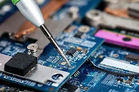
After the repair process, it is crucial to verify that the PCB is functioning properly. Testing helps ensure that the repaired components are working correctly and that no other issues are present. Use a variety of testing tools to evaluate the performance of the repaired circuit.
1. Power-On Testing
After replacing the faulty components, apply power to the PCB. Use a multimeter to check voltage levels at various points to ensure they match the expected values. This step is essential to confirm that the power distribution and voltage regulation circuits are working properly.
2. Signal Integrity Testing
For more complex boards, an oscilloscope can be used to monitor signal integrity across various points on the PCB. Verify that the signals are clean and within the expected range. Signal distortion or noise could indicate further issues that need to be addressed.
3. Functional Testing
Finally, conduct functional tests to ensure that the PCB operates as intended. This may involve testing the functionality of the entire system or focusing on specific parts of the circuit, such as audio or communication functions.
Example: After replacing the faulty resistor in the audio circuit, connect the repaired PCB to a power supply. Use a multimeter to check the voltage at key points. Then, use an oscilloscope to verify that the audio signal is consistent and free from distortion. If the signal is intact and within specifications, the repair is successful.
Conclusion
With this step-by-step guide, you are now equipped with the knowledge and instructions to confidently repair circuit boards. By understanding components, identifying issues, mastering soldering techniques, and following safety measures, you can successfully troubleshoot and repair circuit boards. It may be helpful to practice the techniques mentioned on less critical or disposable boards before attempting repairs on valuable or critical circuit boards. Remember to practice caution and continuously expand your knowledge in circuit board repair.

