When designing the packaging for electrolytic capacitors, it is crucial to include clear indicators that show the correct orientation of the component. The importance of polarity in these capacitors cannot be overstated. Incorrect polarity not only risks damaging the capacitor but can also harm other components on the circuit board. The success of a product often hinges on the precision and clarity of component markings.
Electrolytic capacitors are polarized, meaning they have positive and negative terminals, and it is essential to mark the PCB with indicators that ensure the correct placement of the component. Improper placement can compromise the dielectric performance of the capacitor, leading to a shortened lifespan or, in the worst case, immediate failure.
Clear and consistent component markings are vital to the smooth manufacturing process, ensuring that the capacitor does not fail prematurely. Beyond their direct functional importance, these markings help simplify the PCBA assembly process. Assemblers and technicians rely on these indicators for efficient component placement. Any ambiguity in the markings can slow down the assembly process or, worse, result in costly mistakes that need to be corrected.
Given the unique construction of tantalum electrolytic capacitors and their sensitivity to reverse voltage, incorrect polarity can lead to catastrophic failure. A reversed polarity not only damages the capacitor but can also harm the surrounding circuit board and other components, underlining the critical need for proper orientation and clear, accurate markings.
Electrolytic Capacitors: Types, Marking Conventions, and Key Design Considerations

Electrolytic capacitors are one of the most commonly used types of capacitors in PCB design due to their ability to store a significant amount of charge relative to their small physical size. Their cost-effectiveness and the balance they strike between physical size and capacitance make them a go-to choice for various electronic applications, especially when space is limited.
Electrolytic capacitors are typically polarized components, meaning they have a specific polarity that must be respected during both design and assembly. The failure to do so can lead to catastrophic damage not only to the capacitor itself but also to the surrounding circuit components. Ensuring the correct orientation is critical for the long-term reliability and safety of the circuit.
There are four primary physical types of electrolytic capacitors commonly used in PCB designs:
- SMT Can (Surface Mount Technology)
These capacitors are designed for surface-mount applications and come with a cylindrical can-like shape. Their markings typically indicate the polarity, with a stripe on the cathode side (negative side). These types of capacitors are generally smaller and are used in compact, high-density circuit designs. - SMT Radial (Surface Mount)
Similar to the SMT can, these capacitors also feature a radial lead structure but are mounted on the surface of the PCB. The polarity is indicated by a band on the negative terminal side. - PTH Radial (Through-Hole)
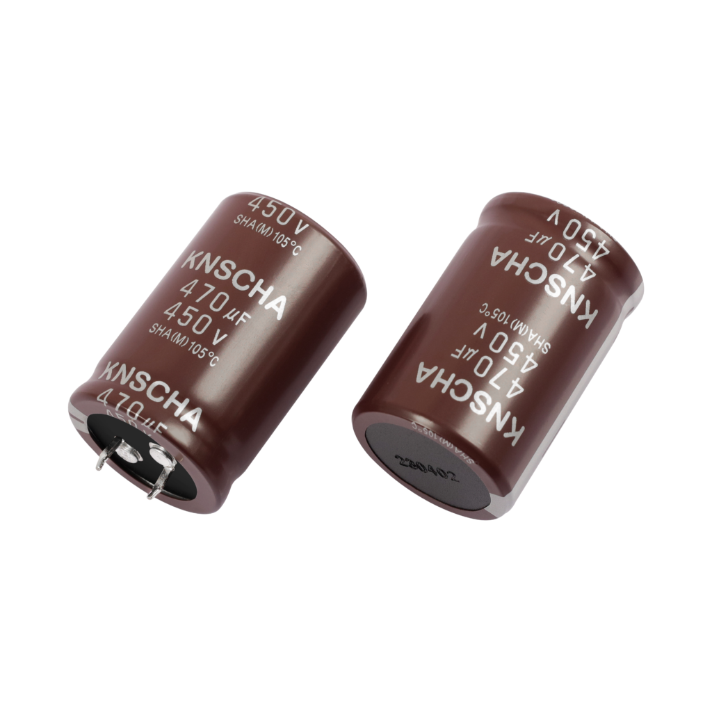
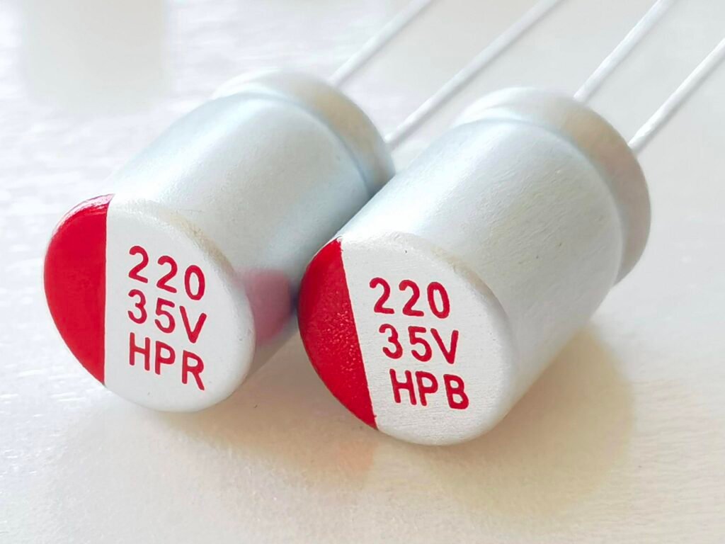
Radial lead electrolytic capacitors have two leads extending from the base of the component, allowing them to be inserted through holes in the PCB. Like their SMT counterparts, the negative terminal is indicated by a stripe or marking, but these components are larger and more commonly found in traditional or high-power circuits. - PTH Axial (Through-Hole)
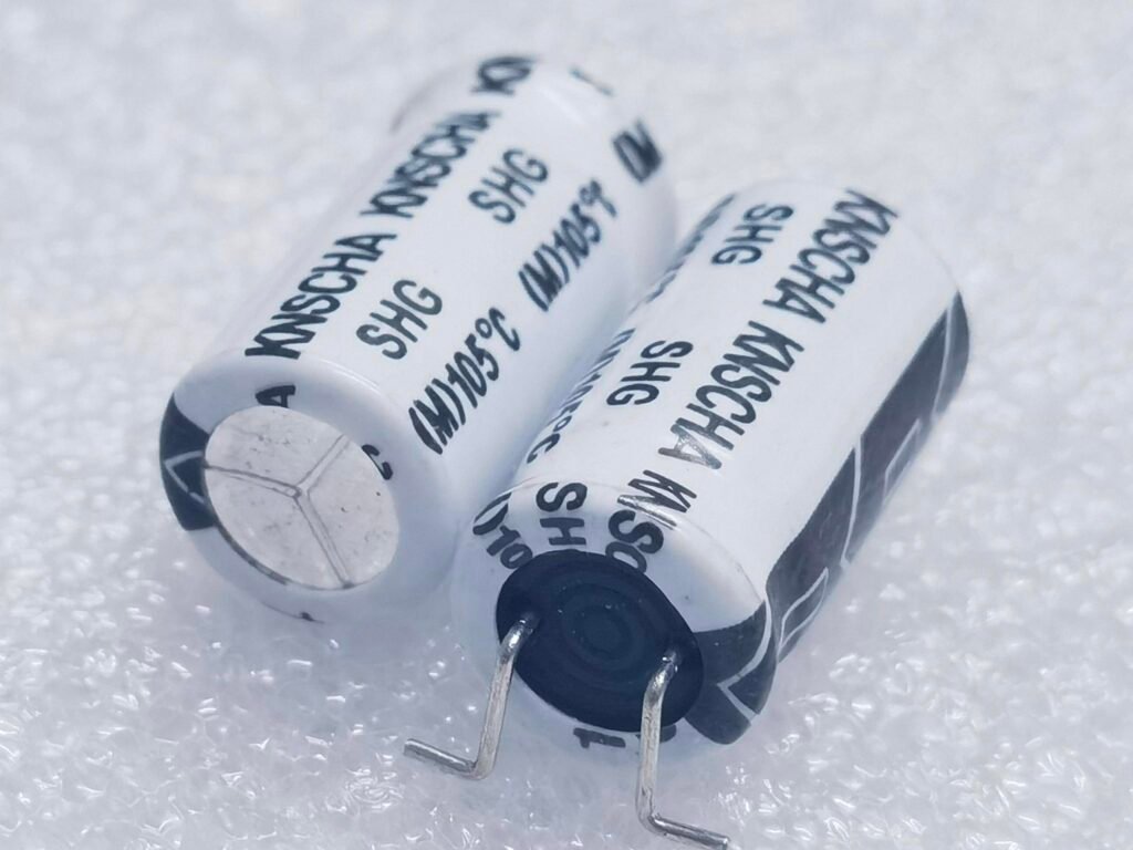
Axial electrolytic capacitors feature leads that extend from both ends of the component, arranged in an axial configuration. These capacitors are often used in power applications and come with polarity markings similar to PTH radial types.
Key Considerations for Marking and Orientation
The key distinction between these types of electrolytic capacitors is their polarity. They are polarized, meaning they have a specific positive and negative terminal, and incorrect placement or incorrect orientation can result in capacitor failure. Generally, capacitors will have a clear indication of polarity, with a stripe or a negative sign (usually on the cathode side).
It is crucial that PCB designers ensure these components are placed correctly on the board, in accordance with their markings. Additionally, manufacturers should verify these polarities during the assembly process to prevent mistakes and guarantee the long-term reliability of the design. Improper polarity may result in failure modes such as leakage, reduced lifespan, or even violent failure of the capacitor.
In some cases, the negative terminal marking on these capacitors may not always be the traditional stripe. Therefore, it is important to consult the manufacturer's datasheet to understand the exact marking and polarity for each specific part number.
By paying attention to proper marking and orientation during both the design and assembly phases, manufacturers can avoid the risks associated with misplacing or incorrectly orienting electrolytic capacitors on PCBs. This attention to detail ultimately helps in ensuring circuit performance, reliability, and safety.
Electrolytic Capacitor Schematic Symbols: Understanding Polarity and Consistency

In schematic diagrams, it is essential to represent polarized components, like electrolytic capacitors, accurately to ensure proper functionality during assembly and operation. Electrolytic capacitors have polarity, meaning they must be installed in a specific orientation to avoid damage to the capacitor or other components in the circuit. The correct symbol and its consistency are crucial to conveying this information to anyone reviewing or assembling the design.
Schematic Symbol for Electrolytic Capacitors
The typical schematic symbol for a polarized capacitor (such as an electrolytic capacitor) consists of two main components:
- The Anode (+) Marking:
The positive terminal, or anode side, of the electrolytic capacitor is represented by a straight line on the symbol, usually accompanied by a “+” sign to indicate its polarity. This is crucial because the anode is the side that must be connected to the higher potential in the circuit. - The Cathode (–) Marking:
The negative terminal, or cathode side, is usually represented by a curved line and may be marked with a stripe or a “-” sign, depending on the convention used by the manufacturer. This symbol indicates that this side must be connected to the lower potential, or ground, of the circuit.
Consistency in Symbol Usage
Maintaining consistency in the use of these symbols is essential for clarity and accuracy in the schematic. When designing a circuit, always use the same format for polarized components to ensure that anyone reading the schematic—whether it’s a colleague, a technician, or a manufacturer—can immediately identify the correct polarity. This is particularly important in high-volume manufacturing, where assembly errors due to misinterpreted symbols can lead to costly mistakes.
While the symbols for electrolytic capacitors are standardized, some minor variations may exist depending on the design software or manufacturer’s conventions. It's always advisable to refer to the manufacturer’s datasheet for detailed information on symbol conventions, especially when using components with unique packaging or configurations.
Importance of Correct Polarity in Schematic Design
In polarized capacitors, the anode and cathode must be correctly oriented on the PCB, as they cannot function properly if reversed. Incorrect placement can result in capacitor failure, leakage, overheating, or even catastrophic failure, potentially damaging the entire circuit. Using a clear and consistent symbol in the schematic helps designers and engineers avoid such risks by emphasizing the importance of polarity.
Additionally, when reviewing and approving designs, clear marking of polarity ensures that assembly technicians or automated placement machines can quickly and accurately place components. This reduces the chance of human error and prevents costly mistakes on the production floor.
By adhering to proper schematic conventions and maintaining clarity in marking the polarity of electrolytic capacitors, PCB designers can ensure that their designs are not only functional but also easy to assemble, minimizing errors and enhancing the overall quality of the product.
SMT Electrolytic Capacitors: Marking and Packaging Overview

Electrolytic capacitors, particularly in surface-mount technology (SMT) configurations, are commonly used in modern PCB designs due to their ability to offer high capacitance values in compact packages. These capacitors come in various forms, including SMT cans, SMD electrolytic, and PTH (pin-through-hole) configurations. Each type requires specific considerations in terms of marking, orientation, and packaging for proper installation and circuit functionality.
SMT Can-type Electrolytic Capacitors
SMT can-style electrolytic capacitors typically feature a distinct marking on the top, which is often black but may vary by manufacturer. The marking helps to identify the polarity of the capacitor, with the black line usually indicating the negative (cathode) terminal. On the positive (anode) side of the capacitor, the plastic base is often beveled or chamfered for easier orientation during placement on the PCB.
- Polarity Marking: The negative side of the capacitor is clearly marked, typically by a stripe or line around the edge of the capacitor’s metal casing.
- Manufacturing Variations: While the standard marking is black for the cathode, it’s essential to consult the manufacturer's datasheet for exact marking conventions, as colors and patterns can vary.
- Mounting and Placement: SMT can-style capacitors are designed for automatic pick-and-place machinery, where the correct orientation based on the markings ensures accurate placement during assembly.
SMT Electrolytic Capacitor Packaging
- Footprint and Layout: These capacitors have a specific footprint on the PCB that must be accurately adhered to for proper fitting. The PCB layout should include pads that accommodate the physical size and mounting requirements of the SMT can capacitor.
- Electrolyte Composition: Most SMT electrolytic capacitors use a liquid electrolyte, but some models may incorporate solid electrolytes or conductive polymers for improved performance and longevity.
SMT External Package Electrolytic Capacitors
This type of capacitor is typically constructed with tantalum or niobium, though certain models may use polymer electrolytes. These capacitors are characterized by their resemblance to other common SMD components, such as resistors and ceramic capacitors. Unlike other types of electrolytic capacitors, the external SMT package often marks the positive (anode) terminal.
- Marking: The anode or positive terminal is clearly indicated on the external packaging. This is an important consideration because it ensures the proper orientation during installation.
- Size and Footprint: SMT external package electrolytics share the same footprint as smaller SMD components like 0805 resistors, making them ideal for compact designs.
PTH Radial Electrolytic Capacitors
Radial electrolytic capacitors are typically used for through-hole mounting, and their polarity is indicated by a distinct contrasting stripe, typically located on the cathode or negative side of the capacitor. This marking ensures that the capacitor is correctly oriented during assembly, as improper placement can lead to malfunction or failure.
- Polarity Stripe: On most radial electrolytic capacitors, a clearly visible band marks the negative terminal. This stripe is essential for ensuring the correct placement of the capacitor within the circuit, as reverse polarity can cause damage to the capacitor and the surrounding components.
- Radial Capacitor Footprint: These capacitors typically require more space on the PCB compared to their SMT counterparts, but they offer higher capacitance values and are suitable for circuits requiring larger component sizes.
PTH Axial Electrolytic Capacitors
Although less commonly used in modern designs, axial electrolytic capacitors offer a unique marking system. The cathode (negative) side is indicated by a band that runs along the length of the capacitor body, similar to radial types, but with an arrow to show which side is negative. This marking method is especially important when the capacitors are placed along the axis of the circuit for easy identification.
- Polarity Marking with Arrow: The negative terminal is indicated by an arrow along the side of the capacitor, pointing to the cathode. This helps ensure that assembly technicians or automated pick-and-place machines can easily identify the proper orientation.
- Axial Capacitor Footprint: Axial capacitors have a linear design and are typically used in applications where space constraints or orientation requirements necessitate a specific mounting method. The marking and footprint for axial components differ from both SMT and radial electrolytics.
Key Considerations for Proper Capacitor Marking and Placement
- Consistency Across Components: For efficient assembly and accurate orientation, it’s essential to maintain consistent marking conventions for polarized components. This consistency reduces the risk of errors during manufacturing and assembly, particularly when components are handled by automated systems.
- Consulting Manufacturer’s Specifications: As capacitor designs can vary, always refer to the manufacturer’s datasheet for specific details on marking colors, stripe orientations, and packaging dimensions. Misinterpretation of these markings can result in assembly mistakes that lead to costly rework.
- The Importance of Proper Polarity: Ensuring that capacitors are correctly oriented is critical for the longevity and performance of the circuit. Improper placement of a polarized capacitor can result in short-circuiting, overheating, or even catastrophic failure of the capacitor and the surrounding circuit components.
Conclusion
Proper marking and packaging of electrolytic capacitors are crucial for ensuring reliable and efficient PCB assembly. Understanding the specific types of capacitors, such as SMT can, SMT external, PTH radial, and PTH axial, and ensuring the correct polarity markings are followed during design and manufacturing will contribute to the overall success of your circuit. By adhering to standardized practices and checking the manufacturer’s specifications, you can avoid common assembly issues and improve the overall reliability of your electronic products.


