
Printed circuit boards sit at the core of almost every electronic product today. I learned this early in my manufacturing work, where every design — simple or complex — begins with the right PCB structure.
A PCB is a board that connects electronic components using copper traces. Different PCB types—such as single-layer, double-layer, and multi-layer—fit different performance, size, and durability needs.
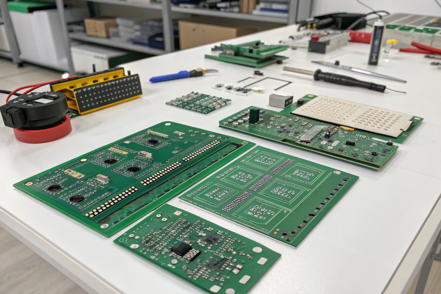
Before choosing materials or sending files for manufacturing, it’s important to understand what PCBs are made of and how each board type affects cost, size, heat, and stability. This helps you avoid redesigns later and speeds up the journey from idea to working hardware.
What is a PCB and how does it work?
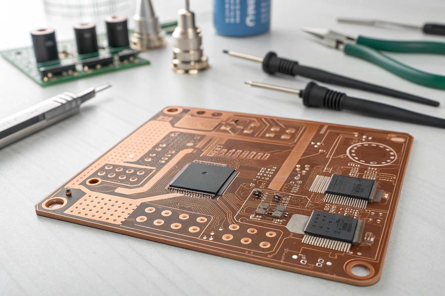
When I built my first prototype years ago, I still remember how confusing all the layers looked. Once I understood the structure, everything became easier.
A PCB works by using copper layers to form electrical connections between components, replacing traditional wiring while keeping the design stable, compact, and easy to produce.
Understanding PCB structure and why it matters
A PCB is more than a green board. It is a layered system designed to move power and signals safely. The basic stack includes:
| Layer | Description | Importance |
|---|---|---|
| Copper layer | Conductive pathways | Carries signals and power |
| Substrate (FR4, etc.) | Insulating base material | Gives the board strength and heat resistance |
| Solder mask | Protective coating | Prevents short circuits |
| Silkscreen | Printed labels | Helps identify components |
| Via system | Vertical copper connections | Links layers internally |
When customers send me new designs, most early problems relate to misunderstanding layer functions—too much current on thin copper, buried returns under splits, or unnecessary complexity. Once these are fixed, boards become more stable.
In my factory, we always review layer stack-up, dielectric values, copper thickness, and thermal paths before production. This check helps avoid issues like warpage or unstable impedance during fabrication.
What are the main types of PCBs?
When I speak with engineers, one of the first questions they ask is: “Which PCB type should I choose for my product?” Choosing the wrong one can increase cost or limit performance.
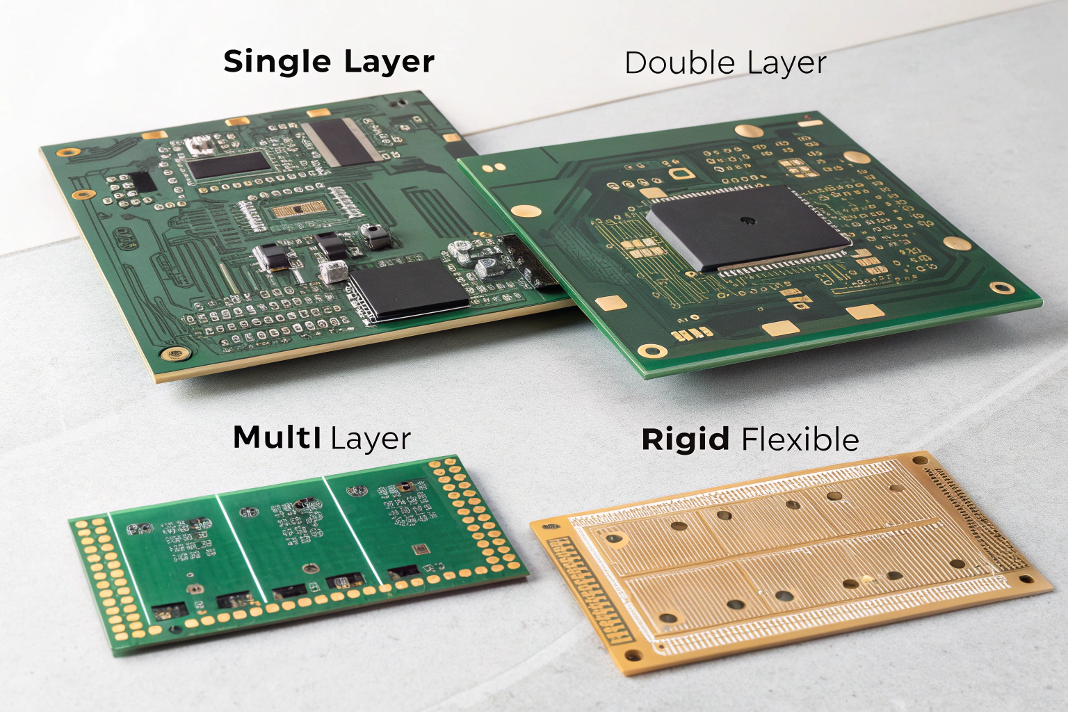
Common PCB types include single-layer, double-layer, multi-layer, rigid, flexible, and rigid-flex boards, each used for different sizes, functions, and environments.
A detailed look at each PCB type and when to use it
Understanding board types helps you match the right structure to your design.
1. Single-layer PCBs
These have only one copper layer.
Best for: simple power boards, LED modules, basic sensors.
They are cheap and fast to produce. I often recommend them to customers in the early testing stage.
2. Double-layer PCBs
These have copper on both sides.
Best for: small controllers, IoT devices, and mixed-signal boards.
They balance cost and capability.
3. Multi-layer PCBs
These stack many layers (4L, 6L, 8L or more).
Best for: advanced electronics, Wi-Fi modules, industrial control, dense designs.
They allow clearer routing, better EMI control, and smaller size.
4. Rigid PCBs
The most common type.
Best for: almost all consumer and industrial products.
5. Flexible PCBs (FPC)
Made from bendable materials.
Best for: cameras, foldable devices, wearables, connectors.
6. Rigid-Flex PCBs
A hybrid combining rigid and flexible sections.
Best for: compact systems requiring reliability in motion (e.g., drones, robotics).
Below is a quick summary:
| PCB Type | Cost | Complexity | Best Application |
|---|---|---|---|
| Single-layer | Low | Easy | Basic modules |
| Double-layer | Medium | Moderate | IoT boards |
| Multi-layer | Higher | Advanced | High-speed systems |
| Rigid | Standard | Wide use | General electronics |
| Flex | Higher | Special | Wearables, cameras |
| Rigid-Flex | Highest | Complex | Robotics, compact devices |
When customers send me a project, the first thing I check is density and signal type. If the design includes RF, high-speed interfaces, or tight space, a multi-layer structure is usually necessary. My engineering team adjusts stack-up suggestions to avoid EMC failures during testing.
How do different PCB types affect manufacturing and performance?
This is a question I receive often because the choice directly affects heat, size, and stability. Years ago, one of my clients used the wrong stack-up and their Wi-Fi module kept failing EMI tests. Changing to a 4-layer board solved it instantly.
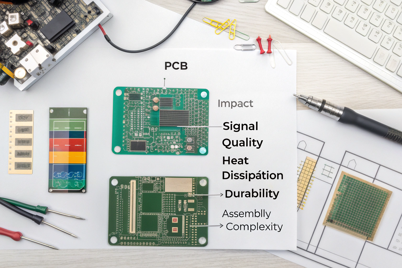
PCB types affect cost, signal quality, heat distribution, durability, and assembly difficulty. Choosing the right type ensures better reliability and faster production.
How PCB structure influences electronics design and final production
Here’s what really changes between board types:
Signal integrity
Multi-layer boards can place signals between ground planes. This reduces noise and improves high-speed or RF performance.
Heat management
Thicker copper and more layers help spread heat better. Power boards often require 2oz copper or more.
Size and component density
Flexible and multi-layer boards allow small footprints and tightly packed circuits.
Mechanical durability
Rigid-Flex boards survive motion and vibration better than connectors and cables.
Assembly efficiency
Boards with proper spacing and clear orientation reduce errors during SMT.
At my factory, we also consider:
- Soldering temperature compatibility
- Via filling or plugging for reliability
- Panel design for better yield
- Test point placement for functional testing
These steps ensure your board performs consistently across many production cycles.
A modern product is more than just a good schematic. Matching the right PCB type with the right manufacturing process can reduce redesigns, assembly issues, and long-term failures. This is why we always provide engineering suggestions—many clients say this support alone saves weeks of debugging.
Conclusion
Understanding PCBs and their different types helps you choose the best structure for your product’s size, speed, and environment. With the right board type and proper engineering support, your design becomes easier to build, easier to test, and more reliable in real use. If you start with the right foundation, every step afterward becomes smoother and faster.
