
The most common mistake in soldering is insufficient heating of the solder joint, which leads to cold solder joints with poor electrical and mechanical reliability.

This mistake appears in hand soldering, SMT reflow, and wave soldering alike. It is not caused by equipment alone, but by incorrect process control, poor thermal balance, and misunderstanding of how solder bonds to metal.
In electronics manufacturing, this single mistake accounts for a large percentage of early failures, rework cases, and field returns. Understanding why it happens is essential for stable production.
Why Are Cold Solder Joints the Most Frequent Failure?
Cold solder joints look connected but are structurally weak.
They often pass basic inspection but fail over time.
A cold solder joint occurs when solder melts without the pad and component lead reaching the proper temperature. The solder solidifies before proper wetting and intermetallic bonding can form.
In production environments, this happens when:
- Preheat temperatures are too low
- Reflow soak time is insufficient
- Boards have heavy copper planes
- Large components absorb heat unevenly
These joints may appear dull, grainy, or irregular. Electrically, they show higher resistance. Mechanically, they crack under vibration or thermal cycling.
In factory assembly lines, cold joints are especially dangerous because they may escape visual inspection and fail months later. This is why temperature profiling and process validation are mandatory steps before mass production.
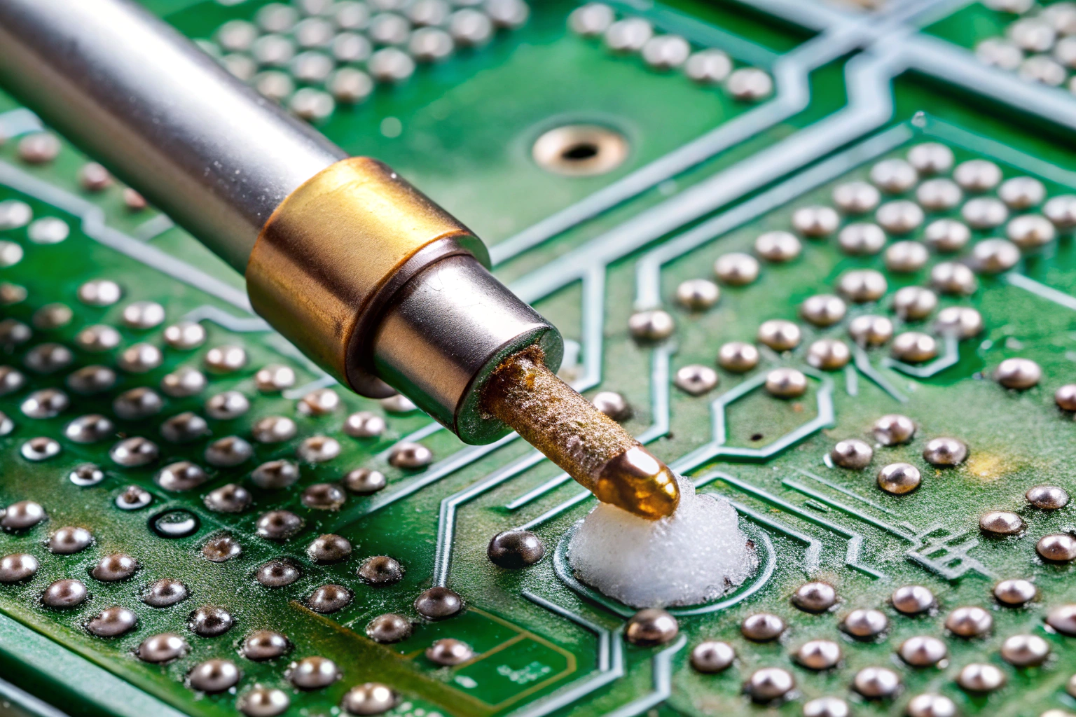
How Incorrect Heat Transfer Causes Soldering Defects?
Heat transfer, not solder quantity, determines joint quality.
Poor heat flow leads directly to failure.
![]()
Many soldering defects are blamed on materials, but the root cause is often uneven heating. Thick PCBs, multilayer designs, and mixed component sizes create thermal imbalance.
If the pad heats slower than the solder, the solder melts prematurely. If the component lead remains cool, solder cannot climb and wet properly.
Manufacturing lines address this by:
- Designing accurate reflow profiles
- Using staged preheat zones
- Controlling conveyor speed
- Matching solder alloy to board design
Wave soldering faces similar challenges. Insufficient preheat causes solder to freeze too quickly. Excessive preheat burns flux and reduces wetting.
Understanding heat flow across the PCB is critical. Without it, even advanced equipment produces unreliable results.
Why Flux Misuse Is a Hidden but Common Soldering Error?
Flux supports soldering, but misuse creates defects.
Both too little and too much flux cause problems.
Flux removes oxides and protects metal surfaces during heating. When flux is insufficient, oxidation blocks solder wetting. When flux is excessive or overheated, residues remain and cause corrosion or leakage.
In manufacturing workshops, flux-related mistakes often come from:
- Incorrect solder paste storage
- Expired or dried paste
- Wrong flux chemistry selection
- Excessive preheat temperatures
Process control prevents these issues. Solder paste is stored under controlled conditions. Open time is monitored. Flux activation temperature is matched to the thermal profile.
AOI systems and ionic contamination testing help detect flux-related risks early. Proper flux management directly reduces rework and long-term reliability issues.
How Poor Process Discipline Leads to Repeated Soldering Mistakes?
Soldering quality depends on consistency.
Lack of discipline multiplies defects.

In manufacturing, repeated soldering mistakes rarely come from a single operator. They come from missing standards and uncontrolled variation.
Common discipline failures include:
- Unverified reflow profiles
- Manual temperature adjustments
- Inconsistent stencil cleaning
- Skipped equipment calibration
Factory workshops solve this with documented procedures. Each product has defined parameters. Changes require engineering approval. Equipment maintenance follows fixed schedules.
Training is equally important. Operators are qualified for specific processes. Visual standards based on IPC guidelines are displayed on-site.
This system approach prevents the same soldering mistake from repeating across batches and shifts.
How Factory Workshop Design Reduces Soldering Errors?
Workshop layout directly affects soldering quality.
Good design supports stable heat and clean flow.

Modern assembly workshops are designed around soldering reliability. SMT lines follow a linear flow from printing to inspection. Environmental controls maintain stable temperature and humidity.
Incoming materials are inspected for solderability. PCBs are stored in dry cabinets. Moisture-sensitive components are baked when required.
Inspection stations are placed immediately after soldering processes. AOI, X-ray, and functional testing catch defects early, before final assembly.
By aligning equipment, people, and environment, factories reduce the chance of cold joints and other common soldering mistakes at scale.
Conclusion
The most common mistake in soldering is insufficient heating of the solder joint, resulting in cold and unreliable connections. This mistake is closely linked to poor heat transfer, incorrect flux behavior, and weak process discipline. In professional manufacturing, stable soldering quality depends on controlled temperatures, clean materials, disciplined workflows, and well-designed factory workshops. When these elements work together, soldering defects drop sharply, reliability improves, and products perform consistently throughout their service life.
