
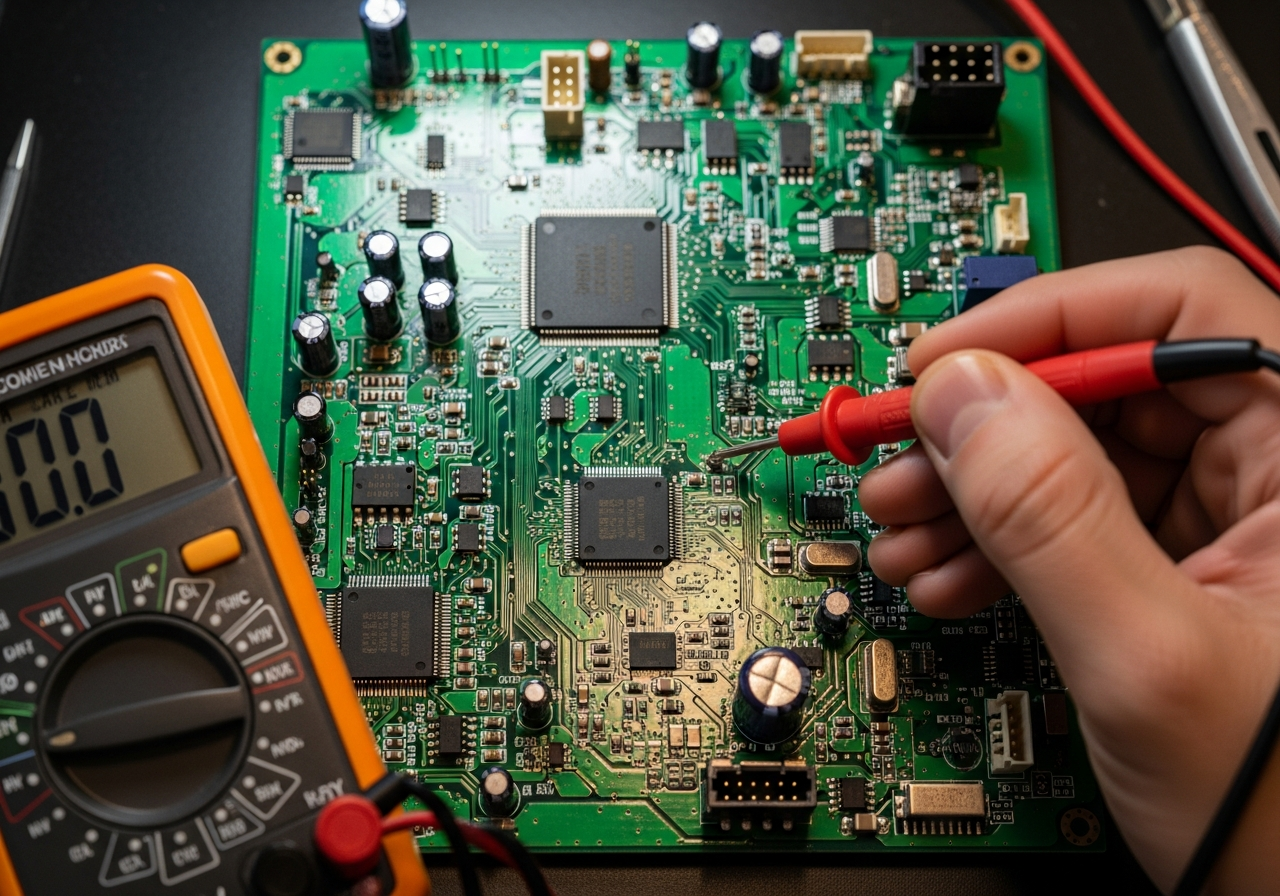
Tracing a PCB with a multimeter is a fundamental diagnostic method used to identify open circuits, shorts, incorrect connections, and damaged traces. This process verifies whether electrical paths on a circuit board match the intended design and remain electrically continuous.
PCB tracing is widely used during failure analysis, rework validation, and quality inspection. In manufacturing, it is a standard step before deeper testing or board replacement decisions.
Correct tracing requires a structured approach. Random probing often creates confusion, false conclusions, or secondary damage.
What Does “Tracing a PCB” Actually Mean?
PCB tracing means following an electrical path.
It confirms where current can and cannot flow.
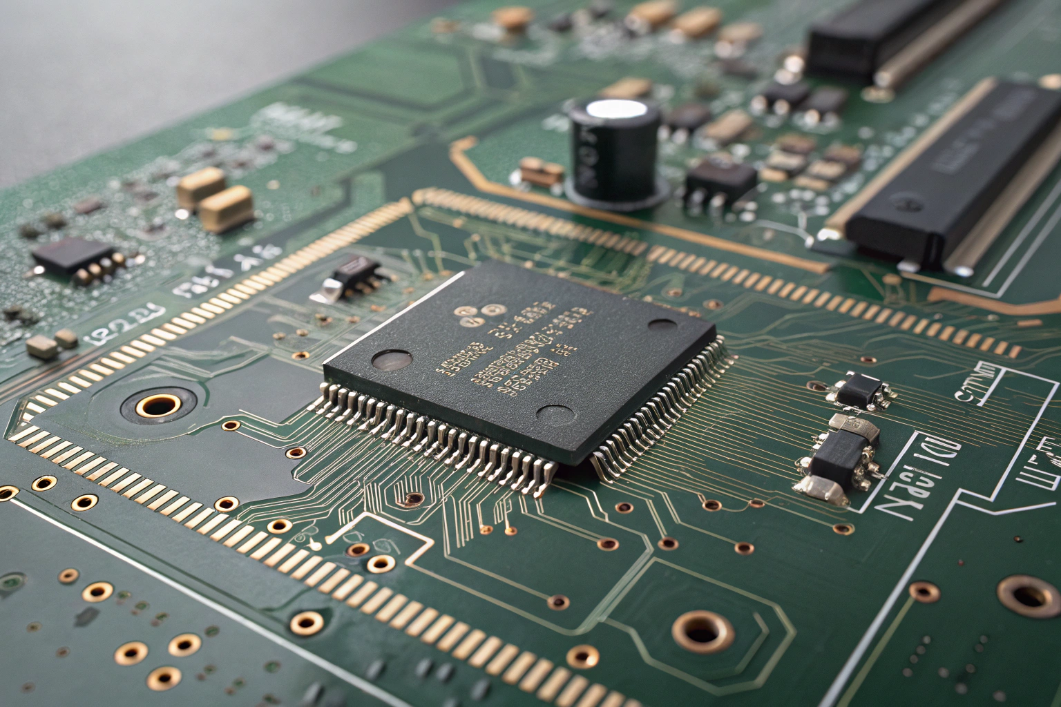
A PCB trace is a copper path that connects components, vias, and connectors. Tracing verifies that:
- Intended connections are continuous
- Unintended shorts do not exist
- Signals reach the correct destinations
Multimeters are used primarily in continuity mode and resistance mode. These modes allow fast confirmation of electrical connections without powering the board.
In factory environments, PCB tracing is often performed after:
- Assembly defects are detected
- Functional test failure occurs
- Rework or repair is completed
Tracing does not replace schematic review or advanced testing. It complements them by confirming the physical reality of the board.
How to Prepare a PCB Before Tracing with a Multimeter?
Preparation determines accuracy.
Skipping steps leads to wrong conclusions.
Before tracing begins, the PCB must be fully powered off. Any residual voltage can damage the multimeter or the board.
Standard preparation steps include:
- Disconnecting all power sources
- Discharging capacitors
- Removing connectors or external loads
- Cleaning visible contamination if necessary
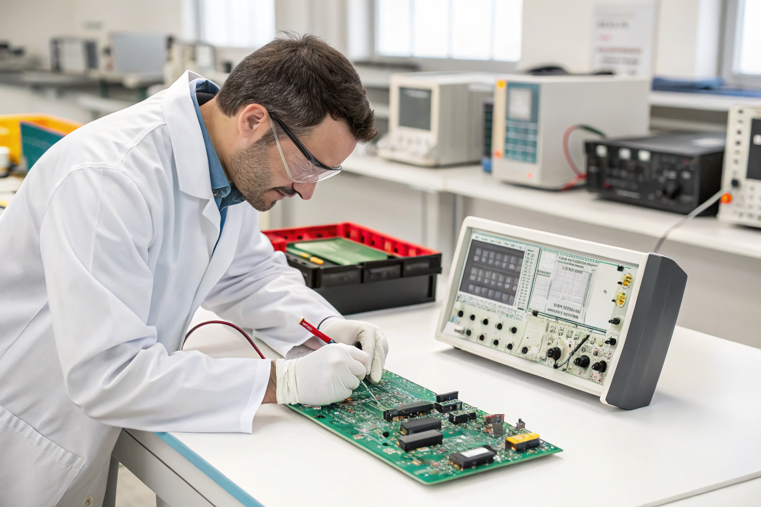
The PCB should be placed on an ESD-safe surface. Probing pressure must be controlled to avoid pad damage, especially on fine-pitch or high-density boards.
In manufacturing workshops, tracing is performed at dedicated diagnostic stations equipped with magnification, proper lighting, and ESD grounding. This environment reduces handling-related risk and improves accuracy.
How to Use Continuity Mode to Trace PCB Connections?
Continuity mode is the primary tracing tool.
It confirms direct electrical paths.
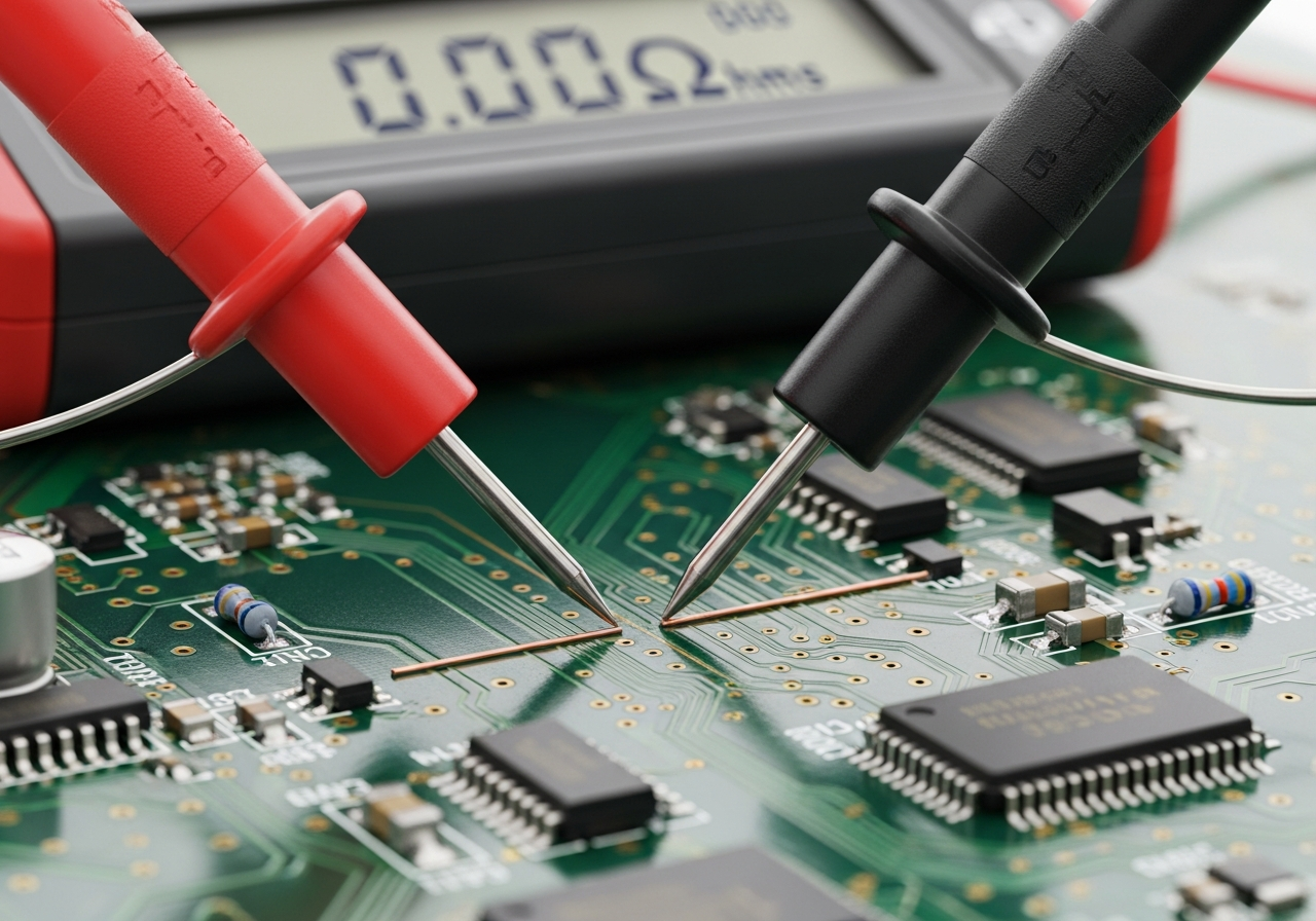
In continuity mode, the multimeter emits a signal when resistance between two points is very low. This indicates a direct electrical connection.
Tracing steps include:
- Placing one probe on a known reference point
- Touching the second probe to suspected connected points
- Listening for the continuity signal
If continuity is present, the trace between those points is intact. If not, an open circuit or broken trace is likely.
In multilayer boards, continuity confirms vertical connections through vias as well as horizontal traces. However, it cannot reveal which internal layer the connection uses.
Manufacturing engineers use continuity tracing to quickly isolate broken traces caused by:
- Mechanical stress
- Overheating
- Pad lifting
- Depaneling damage
How Resistance Measurement Helps Find Partial Failures?
Not all failures are fully open or shorted.
Some traces degrade gradually.
Resistance mode detects abnormal resistance values along a trace. A healthy copper trace shows very low resistance. Increased resistance often indicates:
- Hairline cracks
- Corrosion
- Burned or thinned copper
- Poor solder joints
By comparing resistance readings across similar traces or reference boards, abnormal paths can be identified.
In manufacturing failure analysis, resistance measurement is used to detect latent defects that continuity mode alone may miss. These defects often cause intermittent failures under load or temperature change.
This method is especially valuable for power paths and ground networks, where small resistance increases lead to voltage drop and overheating.
How to Trace Shorts and Unwanted Connections?
Short circuits are traced differently.
The goal is to find unintended continuity.
To trace a short:
- Measure continuity between power and ground
- Probe neighboring pads and traces
- Compare against known-good boards or schematics
If continuity exists where it should not, the short location must be narrowed step by step. Magnification often reveals solder bridges, solder balls, or damaged solder mask.
In factory workshops, tracing shorts is often combined with visual inspection and thermal observation. In some cases, localized heating reveals the short location faster than probing alone.
Once a short is confirmed, root cause analysis determines whether repair is acceptable or replacement is required.
How Multimeter Tracing Fits into Factory Process Control?
Tracing is part of a larger quality system.
It supports decision-making, not guesswork.
In professional manufacturing, multimeter tracing is integrated into:
- Incoming inspection verification
- In-process defect analysis
- Rework validation
- Failure analysis reports
Tracing results are documented and linked to serial numbers. Repeated trace failures trigger upstream investigation into PCB fabrication, assembly parameters, or handling processes.
Factory engineers do not rely on tracing alone. Results are correlated with AOI, X-ray, and functional test data. This ensures that conclusions are accurate and corrective actions address the real cause.
Controlled tracing reduces unnecessary rework and prevents unstable boards from entering later production stages.
Common Mistakes to Avoid When Tracing a PCB
Good tools still fail with poor technique.
Discipline protects accuracy.
Common tracing mistakes include:
- Tracing on a powered board
- Applying excessive probe force
- Assuming continuity equals correctness
- Ignoring internal layer complexity
- Skipping schematic comparison
In manufacturing environments, these mistakes are minimized through training, standard procedures, and peer verification.
Tracing confirms electrical paths, but it does not replace design intent verification. Results must always be interpreted in context.
Conclusion
Tracing a PCB with a multimeter is a practical and reliable method for identifying opens, shorts, and degraded traces when performed correctly. The process relies on proper preparation, continuity testing, resistance measurement, and structured analysis. In manufacturing, PCB tracing is not an isolated activity but part of a controlled diagnostic workflow supported by ESD protection, documentation, and cross-checking with other inspection methods. When applied with discipline, multimeter tracing accelerates troubleshooting, supports repair decisions, and helps maintain consistent product quality across production and testing stages.
