
Testing whether a Printed Circuit Board (PCB) is working correctly is a critical step in electronic product development and manufacturing. A PCB that looks visually perfect may still fail electrically or functionally if testing is incomplete or poorly structured. Reliable testing ensures product stability, reduces field failures, and protects overall manufacturing quality.
PCB testing is not a single method but a complete system that combines inspection, electrical verification, functional validation, and process control. In professional manufacturing environments, testing is deeply integrated into workshop operations, production flow, and quality management systems. The following sections explain how a PCB is tested step by step in a structured and professional way.
What Is the First Step to Check If a PCB Is Working?
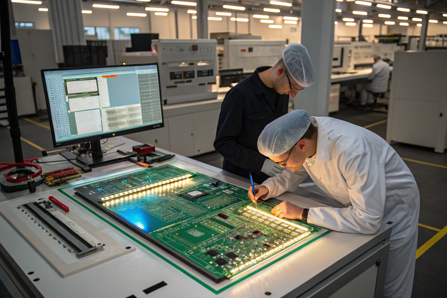
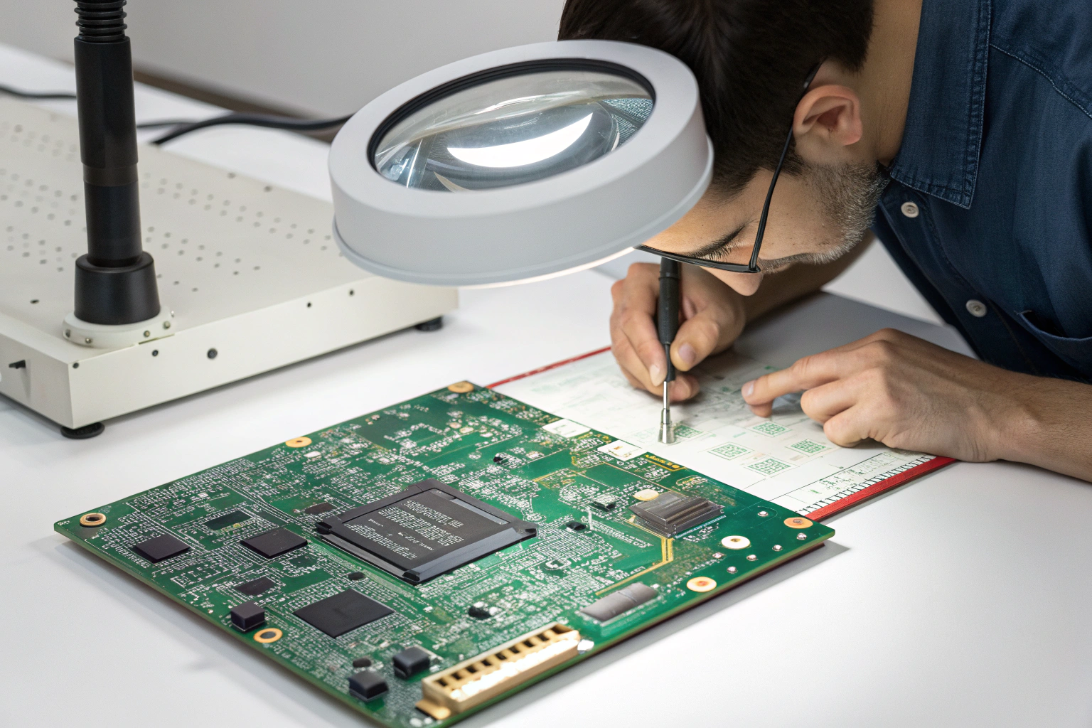
The first step in PCB testing is visual and mechanical inspection. This step detects obvious issues before power is applied, reducing the risk of component damage or short circuits.
Key inspection points include:
- Solder joint quality and uniformity
- Component polarity and orientation
- Missing, shifted, or damaged components
- PCB surface damage, warpage, or contamination
In factory workshops, visual inspection is performed using magnifiers, microscopes, or Automated Optical Inspection (AOI) systems. AOI machines compare assembled boards with reference data to identify solder bridges, insufficient solder, or placement deviations.
Mechanical checks are also performed to confirm connector alignment, mounting hole accuracy, and board thickness compliance. This initial step filters out basic assembly defects and prevents unnecessary electrical testing on defective boards.
How Is Electrical Continuity and Power Integrity Tested?
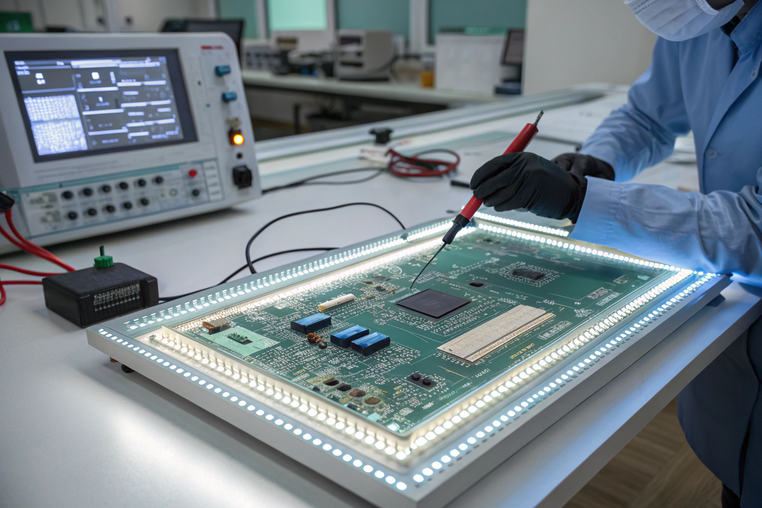
Once visual inspection is completed, electrical testing begins. The goal is to confirm that electrical connections are correct and that power circuits behave as expected.
Typical electrical tests include:
- Continuity testing for open circuits
- Short-circuit testing between power and ground
- Resistance checks on key nets
- Power-on current monitoring
In manufacturing workshops, these tests are often performed using multimeters, flying probe testers, or In-Circuit Test (ICT) fixtures. ICT systems quickly verify thousands of test points on complex boards and detect hidden soldering or connection issues.
Power integrity is especially critical. Before full power-up, current-limited power supplies are used to detect abnormal current draw. Excessive current often indicates shorts, reversed components, or damaged ICs. Controlled power testing protects the board and improves fault isolation accuracy.
How Does In-Circuit Testing Validate PCB Assembly Quality?
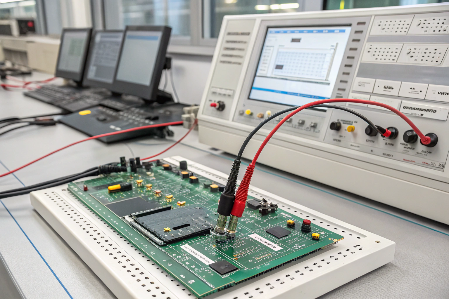
In-Circuit Testing is a key process for verifying assembly quality at scale. ICT focuses on individual components and circuit nodes rather than overall functionality.
ICT typically checks:
- Component presence and value
- Diode and transistor orientation
- Pin-level connectivity
- Basic IC response
In professional SMT factories, ICT fixtures are custom-designed based on the PCB layout. Test coverage is planned during the design stage to ensure critical signals are accessible. This highlights the importance of Design for Testability (DFT).
ICT is highly effective for medium- and high-volume production. It ensures consistent quality across batches and provides clear pass/fail data for quality tracking. When failures occur, ICT data helps engineers quickly locate defective components or solder joints.
How Is Functional Testing Performed on a PCB?
Functional testing verifies whether the PCB performs its intended function under real operating conditions. This step goes beyond electrical correctness and focuses on system-level behavior.
Functional testing may include:
- Power-up sequence validation
- Signal input and output verification
- Communication interface testing
- Load and stress simulation
In factory workshops, Functional Circuit Test (FCT) stations are set up to simulate the end-use environment. Custom test jigs, software tools, and firmware are used to trigger and measure board behavior.
This stage often reveals issues related to firmware, timing, signal integrity, or component tolerance. Functional testing ensures that the PCB not only powers on but also operates reliably under expected conditions. Test results are logged and linked to serial numbers for traceability.
How Do Manufacturing Processes Support Reliable PCB Testing?
PCB testing effectiveness depends heavily on manufacturing process control. Testing is not isolated from production; it is integrated into the entire workshop workflow.
Key process elements include:
- Stable SMT placement accuracy
- Controlled solder paste printing
- Optimized reflow profiles
- ESD-safe handling and storage
Modern SMT workshops use standardized work instructions and real-time monitoring systems. Each testing stage is positioned strategically in the production line to detect issues as early as possible.
For example, AOI is placed after reflow soldering, while ICT and FCT are located after final assembly. This layered testing approach minimizes rework costs and ensures only qualified boards move forward. Manufacturing engineers continuously analyze test failure data to refine processes and improve yield.
How Is Long-Term Reliability Confirmed Through Testing?
Beyond basic functionality, long-term reliability testing ensures that PCBs can withstand real-world conditions over time.
Reliability testing may include:
- Thermal cycling tests
- Burn-in testing under continuous operation
- High-humidity or high-temperature exposure
- Mechanical vibration testing
In manufacturing environments, burn-in tests are commonly applied to critical or high-reliability products. Boards are powered for extended periods to identify early-life failures. Components with marginal performance often fail during this stage rather than after deployment.
Test results are documented and reviewed by quality and engineering teams. These findings guide design improvements, material selection, and process adjustments. Reliability testing transforms testing data into long-term product stability.
Conclusion
Testing if a PCB is working is a comprehensive engineering process that combines inspection, electrical verification, functional validation, and reliability evaluation. When supported by a well-organized workshop, controlled manufacturing processes, and structured testing systems, PCB testing becomes a powerful quality assurance tool rather than a simple pass-or-fail step. A complete testing strategy ensures stable performance, consistent quality, and dependable operation from early samples to full-scale production.
