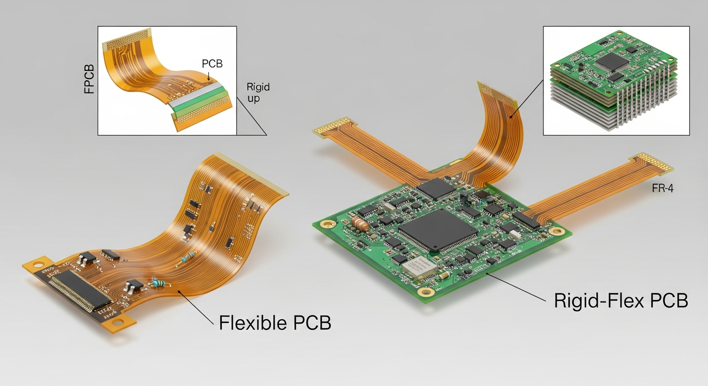
Flexible PCBs and rigid-flex PCBs are bendable circuit solutions designed for compact, lightweight, and high-reliability electronic products. Flex PCBs offer pure bending capability, while rigid-flex boards combine rigid layers with flexible sections to support dynamic movement and strong structural stability.

These technologies allow engineers to design thinner devices, reduce connectors, and improve long-term reliability. They also solve routing challenges where rigid boards cannot fit or where mechanical movement is required.
What are Flexible PCBs?
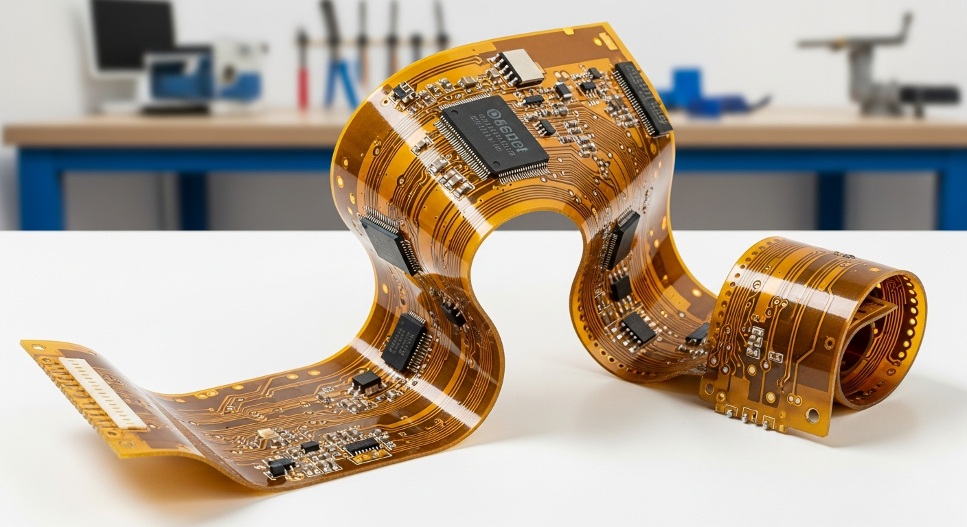
Flex PCBs allow circuits to bend, fold, and twist without breaking. They provide lightweight, thin, and durable interconnect solutions for modern compact devices.
A flexible PCB is a fully bendable circuit made from polyimide material, supporting dynamic flexing, tight bending radii, and compact routing inside space-limited devices.

Deeper Insight
Flexible PCBs use polyimide (PI) substrates instead of rigid FR4. They allow continuous bending, making them useful for wearable devices, cameras, medical probes, printers, battery packs, and compact IoT modules. Their copper traces are designed to withstand repeated mechanical stress, offering high fatigue resistance.
A flex PCB may include:
- Single-layer flex
- Double-layer flex
- Multilayer flex
- Sculptured flex for variable copper thickness
- Stiffeners (PI or FR4) for component reinforcement
Manufacturers evaluate bending radius, copper thickness, and stack-up details during DFM review. Materials such as adhesiveless PI and rolled-annealed copper improve long-term bend performance. For B2B clients developing ultra-thin modules or wearable electronics, flex solutions simplify wiring, eliminate bulky connectors, and improve reliability.
Factories with in-house engineering and SMT capabilities ensure proper pad design, stiffener alignment, and controlled reflow for delicate polyimide substrates. This prevents warpage, delamination, and soldering defects during assembly.
What are Rigid-Flex PCBs?
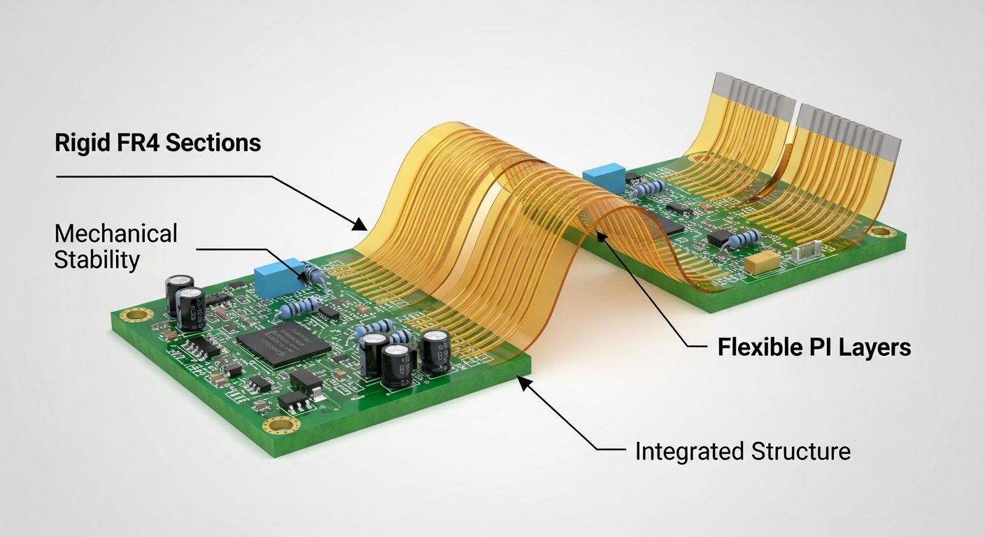
Rigid-flex boards combine stiff FR4 sections with flexible PI layers, enabling both mechanical stability and bendable routing inside the same structure.
A rigid-flex PCB integrates multiple rigid boards connected through flexible layers, forming a single unified structure without connectors.

Deeper Insight
Rigid-flex PCBs support both static posture and dynamic bending. Rigid areas hold components, connectors, or power circuits. Flexible zones form interconnects, reducing the need for cables or soldered wires. This improves signal integrity, simplifies assembly, and enhances long-term reliability.
Common applications include:
- Foldable consumer electronics
- Robotics and automation systems
- Aerospace and defense electronics
- Medical imaging and diagnostic devices
- Smart cameras and gimbal systems
- High-density IoT control boards
Rigid-flex technology enables complex geometries such as 3D routing, multiple bending planes, and Z-axis interconnections. Manufacturers must evaluate microvia integrity, dynamic flex cycles, adhesive layers, coverlay openings, and lamination windows.
In B2B OEM projects, rigid-flex eliminates fragile connectors and avoids assembly error risks. Engineering teams optimize impedance, bending profiles, and layer transitions to create lightweight, durable systems that perform well in harsh environments.
What are the advantages of Flexible PCBs?
Flex circuits reduce bulk, improve durability, and open new design possibilities for compact devices.
Flexible PCBs provide weight reduction, space savings, improved reliability, higher design freedom, and resistance to vibration and mechanical stress.

Deeper Insight
Benefits include:
- Weight & thickness reduction: Often below 0.2 mm
- High bend endurance: Survives hundreds of thousands of cycles
- Improved reliability: Fewer connectors and solder joints
- 3D assembly capability: Folds into tight spaces
- Better vibration resistance: Ideal for mobile and industrial devices
Flex PCBs make assembly easier for wearable devices, compact IoT hardware, and sensor modules. Manufacturers add stiffeners for SMT component areas, reinforcing pads to avoid copper cracking. Engineering reviews check bend radius requirements and select RA copper for flexible zones to ensure long-term durability.
OEM customers benefit from shorter product thickness, simplified wiring, and stable mechanical structure across prototypes and mass-production builds.
What are the advantages of Rigid-Flex PCBs?
Rigid-flex solutions combine robust structure with flexible assembly freedom, supporting advanced product designs.
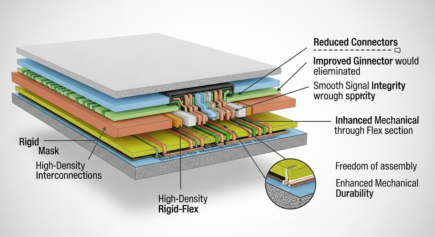
Rigid-flex PCBs reduce connectors, improve signal integrity, enhance mechanical durability, and support high-density interconnections.

Deeper Insight
Key advantages include:
- Elimination of connectors and cables: Increases reliability and reduces failure points
- High-density routing: Supports HDI, buried vias, and microvias
- Improved electrical stability: Shorter interconnect paths
- Mechanical durability: Withstands repeated bending stresses
- 3D product architecture: Supports folding and multi-plane assembly
Rigid-flex PCBs are ideal for robotics, industrial automation, and portable medical devices. They withstand harsh operating conditions and continuous movement. Manufacturers define precise bending zones, layer transitions, and neutral axes. CAM engineers analyze copper balancing, sequential lamination, and controlled impedance requirements.
For B2B clients needing compact, rugged solutions, rigid-flex offers unmatched reliability and long lifecycle performance.
Key Differences: Flexible PCB vs. Rigid-Flex PCB
Although they share similar materials, their structure and applications differ significantly.
Flexible PCBs bend freely, while rigid-flex boards integrate rigid layers for structural support and component mounting.

Deeper Insight
| Feature | Flexible PCB | Rigid-Flex PCB |
|---|---|---|
| Structure | Fully flexible | Rigid + flexible hybrid |
| Components | Limited due to flex | Supports dense component placement |
| Applications | Wearables, sensors, compact modules | Robotics, aerospace, complex electronics |
| Cost | Lower | Higher due to lamination complexity |
| Durability | High bend endurance | Strong mechanical + electrical reliability |
| Design Complexity | Medium | High (requires detailed planning) |
Designers choose flex PCBs when the goal is lightweight, low profile, and simple bending. Rigid-flex is preferred when connectors must be eliminated or the product needs 3D mechanical integration.
Manufacturers evaluate stack-up, stiffeners, adhesive layers, and IPC-6013 class requirements to ensure consistent quality across production runs.
Conclusion
Flexible PCBs and rigid-flex PCBs offer unique advantages for modern electronic products. Flex PCBs enable ultra-thin, bendable designs, while rigid-flex solutions combine mechanical stability with flexible routing for complex, space-constrained systems. By understanding their structures, benefits, differences, and design requirements, engineers can choose the best solution for high-performance and reliable electronic applications. With proper engineering review and manufacturing expertise, both technologies deliver stable performance from prototype to mass production—supporting the next generation of innovative devices.

