
Temperature is one of the most critical factors affecting Printed Circuit Board (PCB) performance and reliability. Every PCB operates within defined thermal limits determined by materials, components, assembly processes, and real working conditions. When these limits are exceeded, failures may occur immediately or develop slowly over time.
In manufacturing environments, PCB temperature is carefully controlled during assembly and closely evaluated during operation. Understanding how hot a PCB can get requires separating short-term process temperatures from long-term operating temperatures and examining how factory processes manage thermal stress.
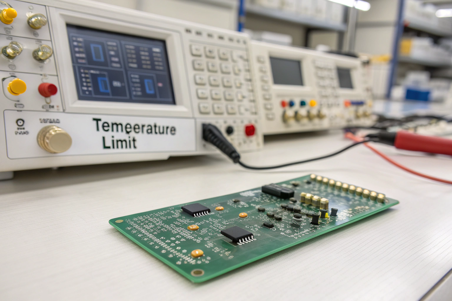
What Is the Normal Operating Temperature Range of a PCB?
The operating temperature of a PCB refers to the temperature the board experiences during normal use after assembly.
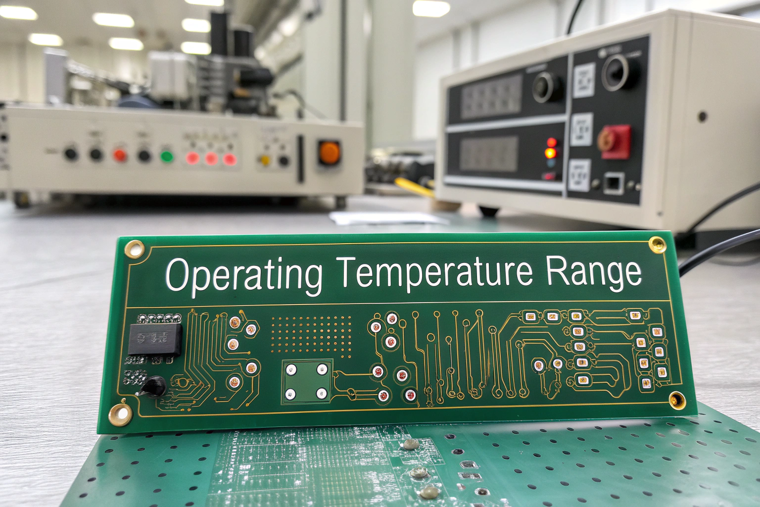
Typical operating temperature ranges include:
- Consumer electronics: 0°C to 70°C
- Industrial electronics: -40°C to 85°C
- High-reliability applications: up to 105°C or higher
These limits are defined by PCB laminate material, solder joint reliability, and component ratings. Even if individual components tolerate higher temperatures, the PCB as a system must remain within safe limits to avoid long-term degradation.
In manufacturing quality standards, sustained operation near the upper limit is treated as a reliability risk rather than a normal condition.
How Hot Can a PCB Get During Manufacturing Processes?
During manufacturing, PCBs experience temperatures far higher than normal operating conditions, especially during soldering.
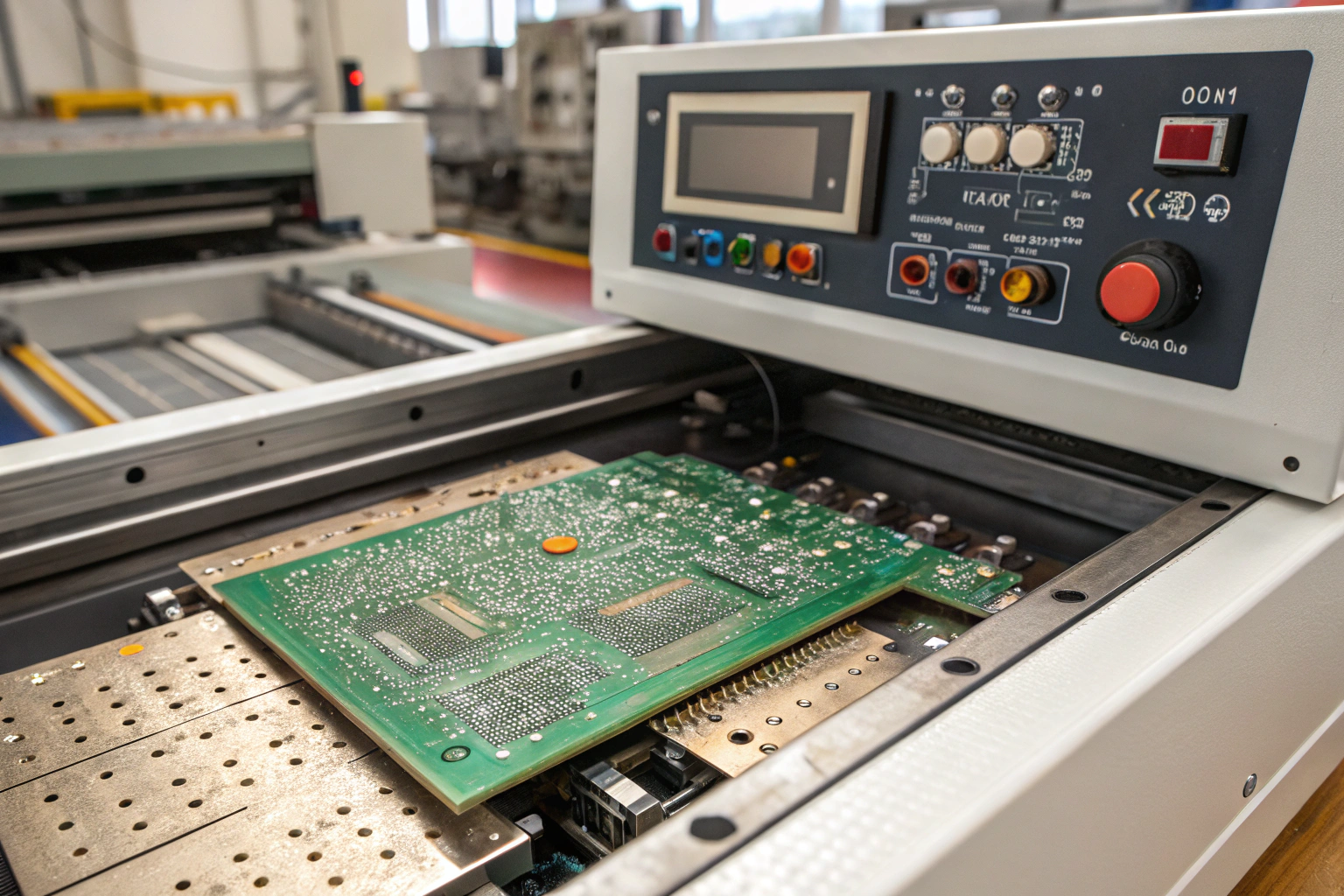
Typical process temperatures include:
- Reflow soldering peak: 230°C to 260°C
- Wave soldering: up to 260°C
- Rework operations: localized heating above 300°C
These high temperatures are applied for short, controlled durations. In SMT workshops, reflow profiles are carefully designed to limit exposure time and prevent thermal damage.
Excessive or repeated heating can cause delamination, pad lifting, or solder joint fatigue. Manufacturing engineers strictly monitor reflow curves and limit rework cycles to protect PCB integrity.
What Happens When a PCB Gets Too Hot in Operation?
When a PCB exceeds its safe operating temperature, multiple failure mechanisms may begin.
Common thermal failure effects include:
- Solder joint fatigue and cracking
- PCB laminate softening or delamination
- Component parameter drift
- Accelerated aging and reduced lifespan
Some failures occur suddenly, such as thermal shutdown or burnt components. Others develop gradually, resulting in intermittent faults that are difficult to diagnose.
In manufacturing environments, overheating during functional testing is treated as a critical warning sign that triggers thermal analysis and design review.
How Do Components Influence PCB Temperature?
A PCB does not heat evenly. Temperature hotspots are usually created by specific components.
Common heat sources include:
- Power regulators and converters
- High-current drivers
- Microcontrollers and processors
- MOSFETs and power transistors
In factory design reviews, component placement and thermal paths are carefully evaluated. Poor layout can trap heat in localized areas, raising PCB temperature well above average board temperature.
Manufacturing engineers review thermal simulation data and functional test results to confirm that component heat dissipation remains within acceptable limits.
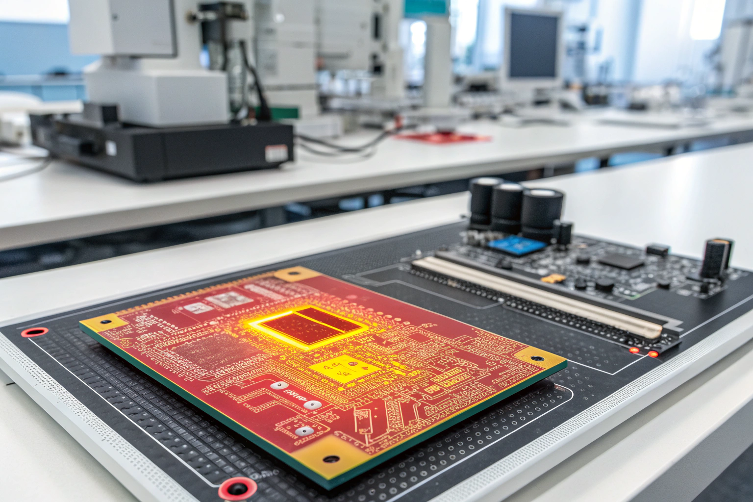
How Do Factory Workshops Control PCB Temperature Risks?
Manufacturing processes play a key role in controlling both assembly and operational thermal risks.
Common factory-level controls include:
- Selection of high-TG PCB materials
- Optimized reflow temperature profiles
- Thermal inspection during testing
- Burn-in and stress testing for hot-running boards
In production lines, infrared imaging or temperature sensors may be used during functional testing to identify hotspots early. Boards that exceed defined temperature thresholds are flagged for further analysis.
Strong process control ensures that thermal issues are detected before mass deployment.
What Is the Maximum Temperature a PCB Material Can Withstand?
PCB material limits are defined by glass transition temperature (Tg) and decomposition temperature (Td).
Typical material limits include:
- Standard FR-4 Tg: 130°C–150°C
- High-TG FR-4: 170°C–180°C
- Decomposition temperature: above 300°C
Operating near or above Tg causes the PCB to lose mechanical strength, increasing the risk of solder joint failure and warpage. Manufacturing standards require sufficient margin between operating temperature and material limits to ensure long-term stability.
Conclusion
A PCB can experience extremely high temperatures during manufacturing, but these exposures are short and tightly controlled. During normal operation, safe PCB temperature is far lower and depends on material selection, component layout, and thermal management. Exceeding operating temperature limits leads to accelerated aging, instability, and eventual failure. In professional manufacturing environments, thermal behavior is managed through material choice, controlled soldering processes, thermal testing, and continuous process monitoring. A mature manufacturing approach does not simply ask how hot a PCB can get, but ensures that it never reaches temperatures that compromise reliability, safety, or product lifespan.
