
Checking a Printed Circuit Board (PCB) with a multimeter is one of the most fundamental diagnostic methods in electronics manufacturing. A multimeter helps identify electrical faults such as short circuits, open connections, abnormal resistance, and incorrect voltage levels. In factory environments, multimeter testing is integrated into inspection, troubleshooting, and rework processes to support quality control and fault analysis.
Although automated testing systems are widely used in production lines, multimeter testing remains essential for confirmation, root cause analysis, and low-volume troubleshooting. The following sections explain how PCBs are checked using a multimeter in a professional workshop setting, combined with manufacturing process considerations.
What Should Be Checked Before Using a Multimeter on a PCB?
Before any electrical measurement, basic preparation is required to avoid damage and ensure accurate results.
Key preparation steps include:
- Confirming whether the PCB is powered or unpowered
- Reviewing schematic diagrams or test points
- Identifying power, ground, and critical signal areas
- Verifying correct multimeter settings
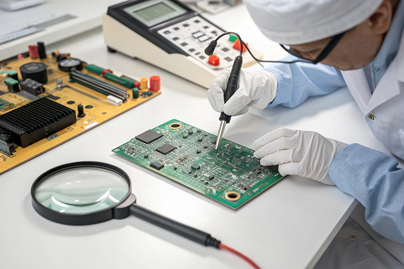
In manufacturing workshops, visual inspection is always performed first. Obvious defects such as solder bridges, missing components, or burnt areas are identified before applying probes. Multimeter testing is never used as a replacement for inspection, but as a complementary verification method.
Power is usually disconnected during initial checks to prevent accidental short circuits or component damage.
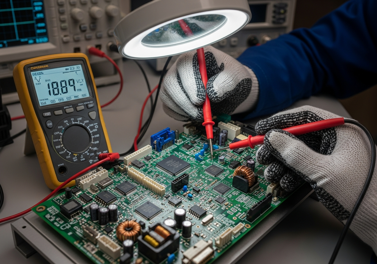
How Is Continuity Testing Used on a PCB?
Continuity testing is one of the most common multimeter functions used to check PCB connectivity.
Continuity testing is used to:
- Detect open circuits in traces
- Verify correct connections between pads
- Confirm connector pin integrity
- Identify broken vias or damaged traces
In factory environments, the multimeter is set to continuity or low-resistance mode. When probes touch two points that should be connected, a stable reading or audible tone confirms continuity.
Failure to detect continuity indicates a broken trace, cold solder joint, or assembly defect. Continuity testing is widely used in rework stations to confirm repair effectiveness before retesting.
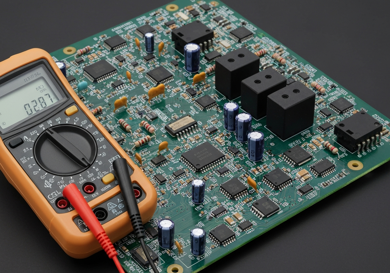
How Is Resistance Measurement Used to Detect PCB Faults?
Resistance measurement helps identify abnormal electrical paths that may not be visible.
Resistance checks are used to:
- Detect short circuits between power and ground
- Verify resistor values
- Identify leakage paths caused by contamination
- Compare suspect boards with known-good samples
In manufacturing workshops, resistance testing is often performed on unpowered boards. A very low resistance between power and ground usually indicates a short circuit. Extremely high or infinite resistance where a connection should exist points to open circuits.
These measurements help narrow down fault locations before more advanced testing or rework begins.
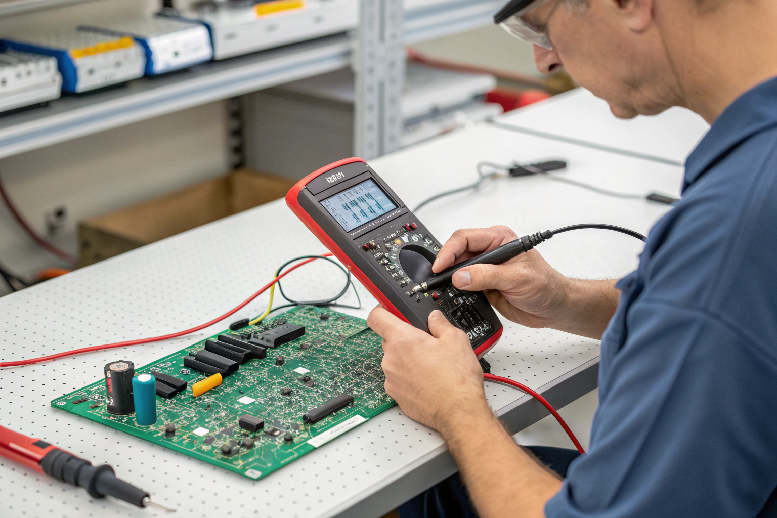
How Is Voltage Measurement Performed on a PCB?
Voltage measurement is used to verify whether power circuits operate correctly under load.
Voltage testing checks:
- Input power levels
- Output voltage of regulators
- Reference voltages for logic circuits
- Signal level stability
In factory settings, voltage measurements are performed using current-limited power supplies to protect the PCB. The multimeter is set to the correct DC or AC range, and probes are placed on defined test points.
Incorrect voltage readings often indicate faulty regulators, incorrect component placement, or power distribution issues. Voltage measurement is a key step in diagnosing control board and power board failures.
How Do Factory Workshops Integrate Multimeter Testing?
Multimeter testing is part of a broader quality and process control system in manufacturing environments.

Workshop integration includes:
- Use in incoming inspection and first-article validation
- Support for AOI, ICT, and functional testing
- Confirmation during controlled rework processes
- Engineering failure analysis and documentation
Although automated testers handle high-volume checks, multimeters provide flexibility and precision for targeted diagnosis. Engineering teams rely on multimeter data to validate repair decisions and confirm root causes identified through other inspection tools.
How Do Manufacturing Processes Improve Multimeter Test Accuracy?
Process discipline plays an important role in ensuring reliable multimeter measurements.
Key process factors include:
- Clearly marked test points on PCB layouts
- Stable grounding and ESD protection
- Proper probe handling techniques
- Consistent test documentation
In professional manufacturing environments, test points are planned during the design stage to support multimeter and automated testing. Clear labeling reduces probing errors and speeds up troubleshooting.
ESD-safe workstations and standardized procedures ensure that multimeter testing does not introduce new faults while diagnosing existing ones.
Conclusion
Checking a PCB using a multimeter is a foundational diagnostic method in electronics manufacturing. Through continuity, resistance, and voltage measurements, multimeters help identify electrical faults quickly and accurately. When combined with visual inspection, controlled power application, and disciplined workshop processes, multimeter testing becomes a powerful tool for fault isolation and quality assurance. In a professional manufacturing environment, multimeter testing supports repair validation, process improvement, and long-term product reliability, ensuring that PCBs meet electrical and functional requirements before moving forward in production.
