
How to Tell If a Control Board Is Bad:
A control board is the core decision-making unit of an electronic system. When a control board becomes faulty, the entire product may stop functioning, behave unpredictably, or fail intermittently. In manufacturing environments, identifying a bad control board is a structured engineering task that combines inspection, electrical testing, functional validation, and process review.
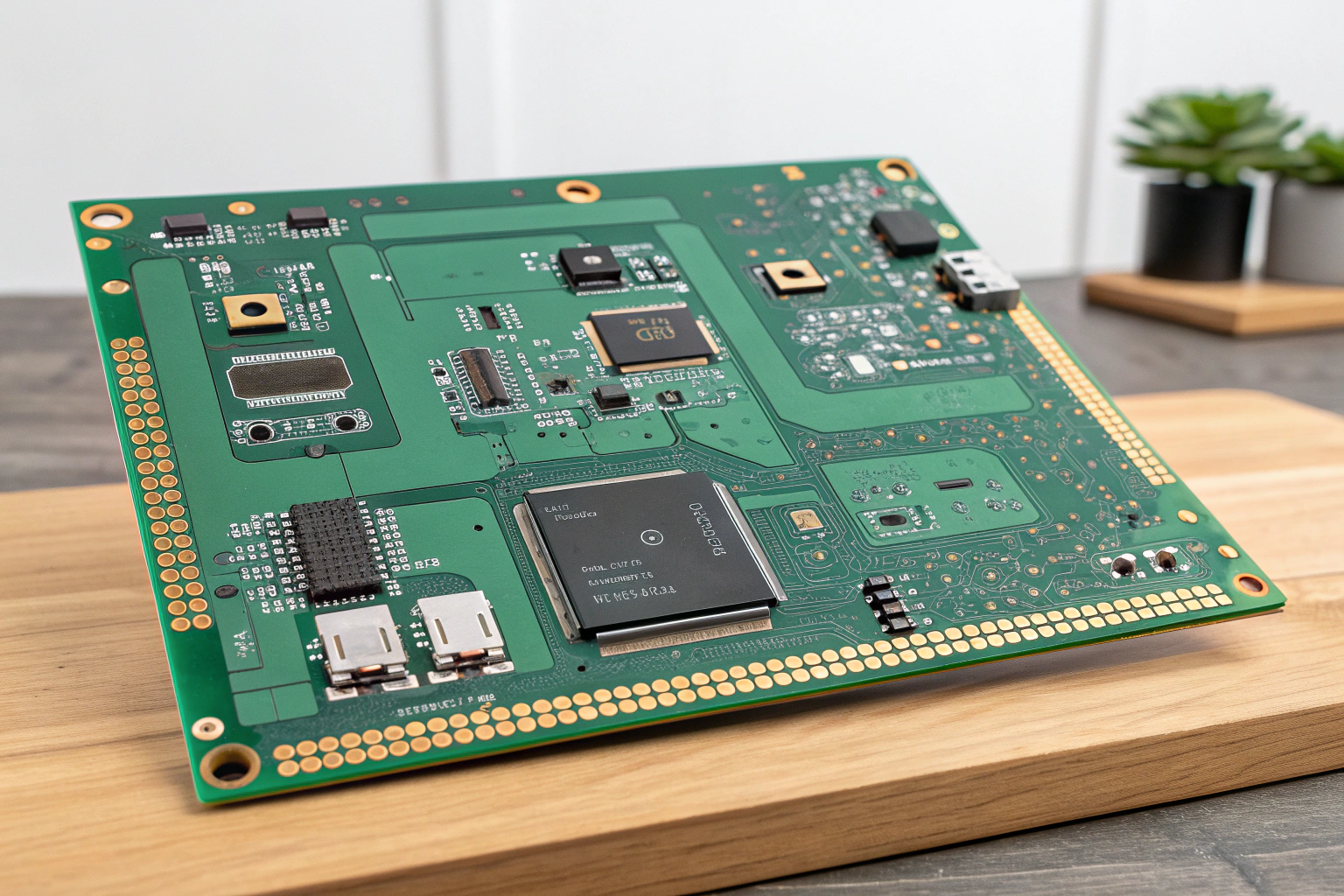
A control board rarely fails without warning signs. Abnormal behavior often reflects deeper issues related to components, assembly quality, power integrity, or process control. The following sections explain how a bad control board is identified using professional methods applied in factory workshops and production lines.
What Are the Common Symptoms of a Bad Control Board?
A bad control board typically shows symptoms that affect system operation rather than isolated functions.

Common symptoms include:
- No power-up or incomplete startup sequence
- Random resets or unstable operation
- Unresponsive inputs or outputs
- Communication failure with peripherals
- Overheating in specific areas of the board
In manufacturing testing stages, these symptoms are often detected during functional testing or system integration tests. A board that powers on but fails to control loads correctly may indicate logic, timing, or firmware-related issues. Symptom classification helps engineering teams determine whether the fault is related to hardware, assembly, or process deviation.
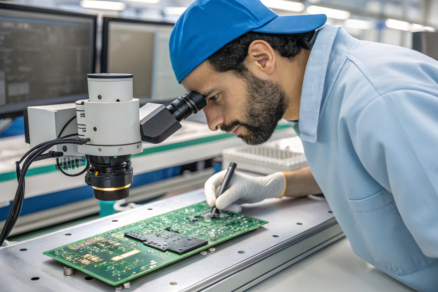
How Does Visual Inspection Reveal Control Board Issues?
Visual inspection is the first step in control board evaluation and often reveals assembly-related defects.
Inspection focuses on:
- Solder joint quality on key components
- Component polarity and orientation
- Burn marks or discoloration
- Lifted pads, cracked components, or contamination
In factory workshops, inspection is supported by magnification tools or Automated Optical Inspection (AOI) systems. AOI detects solder bridges, insufficient solder, and placement errors that may not be visible to the naked eye.
Although visual inspection cannot confirm all faults, it prevents damaged or poorly assembled boards from entering electrical testing, reducing further risk and troubleshooting time.
How Is Power Circuit Testing Used to Judge Board Health?
Power integrity is fundamental to control board operation. Many control board failures originate in the power supply section.
Key power tests include:
- Input voltage verification
- Current consumption monitoring
- Voltage regulator output measurement
- Ground reference stability checks
In manufacturing environments, current-limited power supplies are used during initial power-up. Abnormal current draw often indicates short circuits, damaged components, or incorrect assembly.
If power rails are unstable or missing, the control board is classified as faulty even if no visible damage is present. Power testing provides a clear and objective method to determine whether the board can operate safely.
How Do Functional Tests Confirm a Bad Control Board?
Functional testing verifies whether the control board performs its intended control logic under real operating conditions.
Functional checks may include:
- Input signal response validation
- Output control accuracy
- Timing and logic sequence verification
- Communication interface testing
In factory workshops, Functional Circuit Test (FCT) stations simulate actual operating environments. Custom test fixtures, software, and firmware are used to monitor board behavior in real time.
A control board that passes electrical tests but fails functional tests is still considered bad. Functional testing ensures that hardware, firmware, and assembly work together as designed.
How Do Manufacturing Processes Affect Control Board Reliability?
Manufacturing process quality has a direct impact on control board performance and failure rates.

Critical process factors include:
- SMT placement accuracy
- Solder paste printing consistency
- Reflow temperature profile control
- ESD protection and handling discipline
In professional workshops, machines are calibrated regularly and process parameters are monitored continuously. When control board failures occur, engineers review process data such as reflow curves, placement logs, and inspection records.
Many control board faults trace back to subtle process deviations rather than design errors. Strong process control reduces these risks and improves long-term board stability.
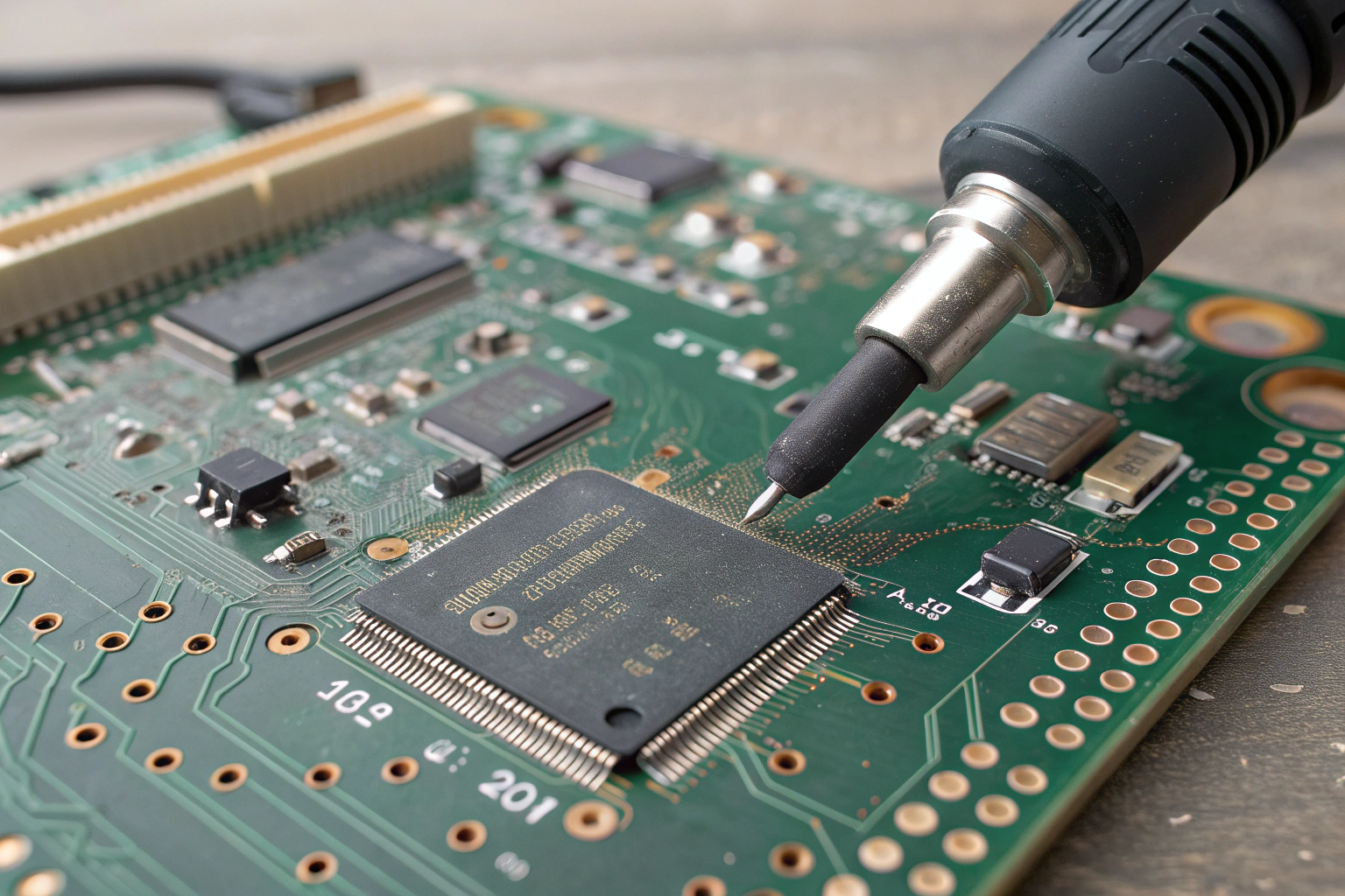
How Is Final Fault Confirmation and Analysis Performed?
Once a control board is suspected to be bad, it enters a structured fault confirmation and analysis process.
Typical steps include:
- Failure replication and documentation
- Root cause analysis by engineering teams
- Controlled rework or component replacement
- Full retesting and validation
- Process corrective action implementation
Rework is performed in dedicated areas using ESD-safe tools and controlled temperatures. Each repaired board must pass the same testing standards as original production units.
Fault data is fed back into design guidelines, assembly instructions, and testing strategies to prevent recurrence.
Conclusion
A bad control board is identified through a combination of symptom analysis, visual inspection, power integrity checks, functional testing, and manufacturing process review. In professional manufacturing environments, a control board failure is treated as both a product issue and a process signal. By applying structured testing methods, disciplined workshop controls, and thorough fault analysis, control board defects can be detected early and reduced over time. A mature manufacturing approach focuses not only on identifying bad boards but also on strengthening processes to ensure stable, reliable control board performance throughout the product lifecycle.
