
An SPDT relay uses one common terminal to switch between two output paths, enabling control of two circuits with a single input signal.
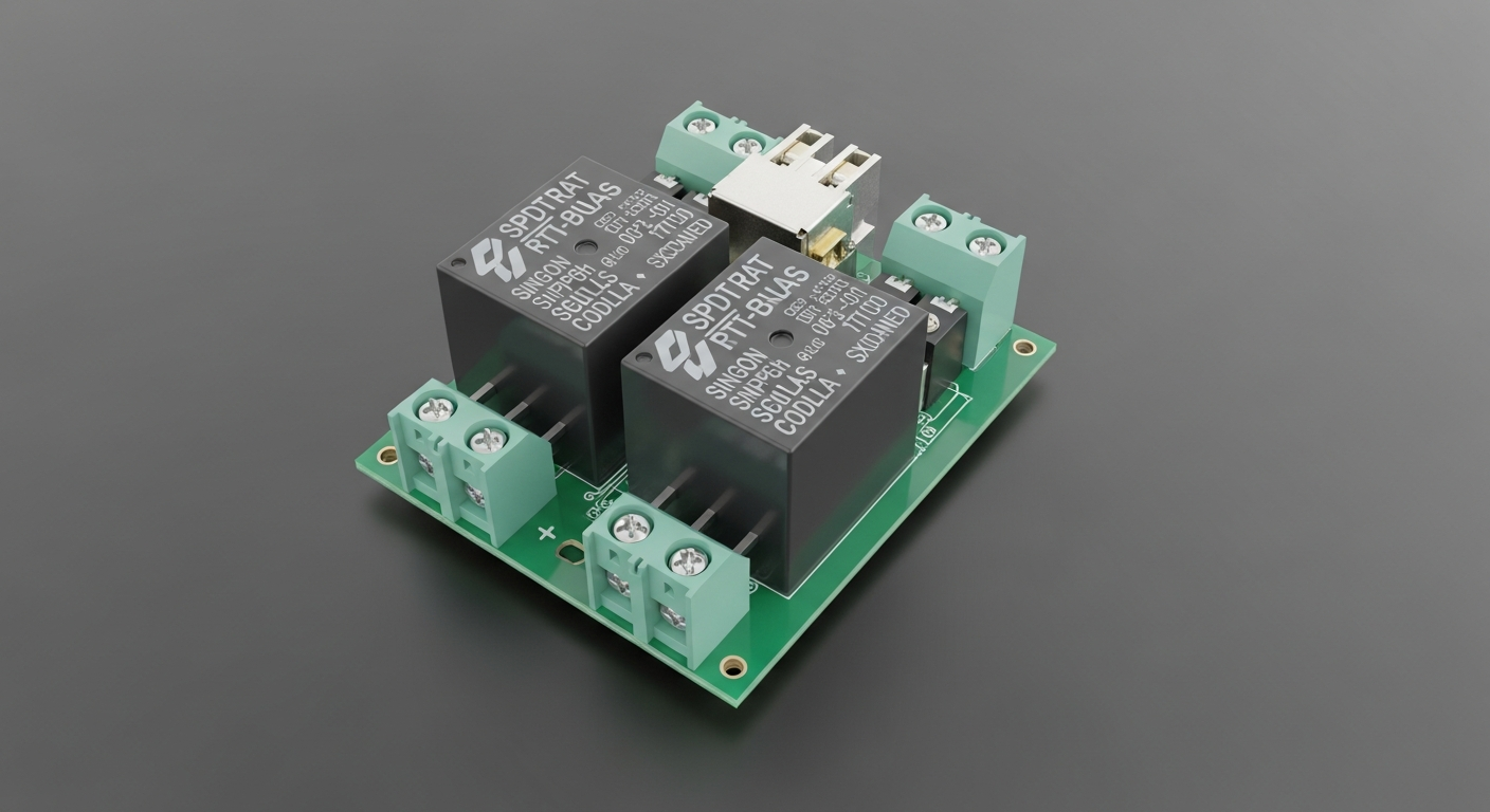
Understanding SPDT relays helps engineering teams build reliable switching systems, manage loads safely, and design PCBA layouts that support stable long-term performance.
What does an SPDT relay do in an electronic circuit?
Incorrect relay selection often causes switching noise, load failure, or unstable device behavior.
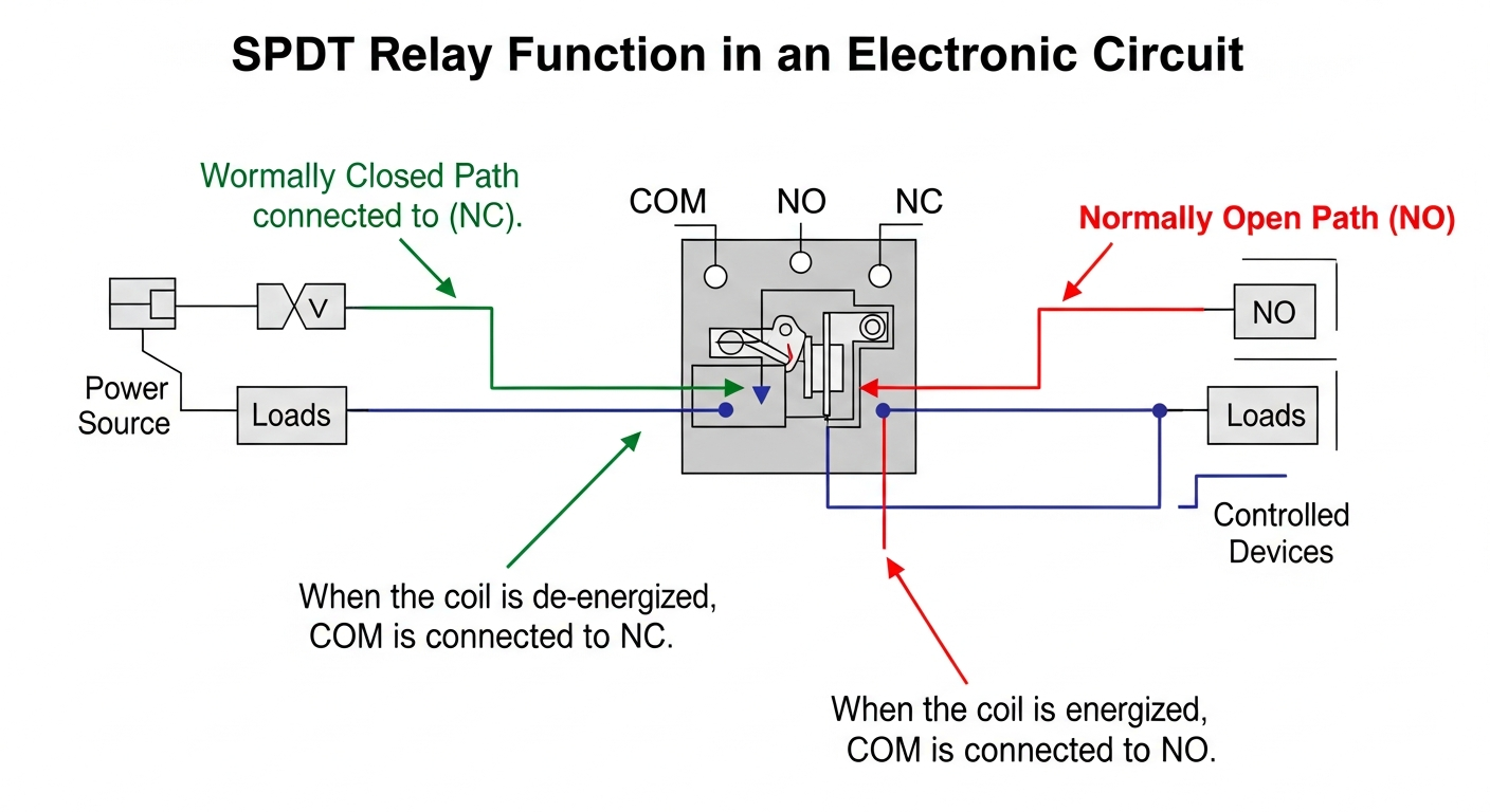
An SPDT relay switches one input (COM) between two outputs (NO and NC), allowing control of dual pathways.
Switching Paths, Control Logic, and Load Flexibility
An SPDT relay consists of one movable contact connected to COM, which can switch between normally closed (NC) and normally open (NO) terminals. When the coil energizes, the armature shifts from NC to NO. This allows a single signal to route power between two loads or operational states.
Such relays support AC/DC loads, motor direction control, lighting systems, and safety mechanisms requiring predictable switching.
In B2B hardware development, poor coil drive design, wrong contact ratings, or low clearance often cause overheating or early field failures. Engineering-driven factories review relay footprints, check pin spacing, confirm coil voltage stability, and optimize PCB trace widths. This reduces risk during SMT/DIP assembly and ensures reliable performance across prototypes and production batches.
How is an SPDT relay constructed?
Unclear internal structure makes troubleshooting more difficult during testing or certification.
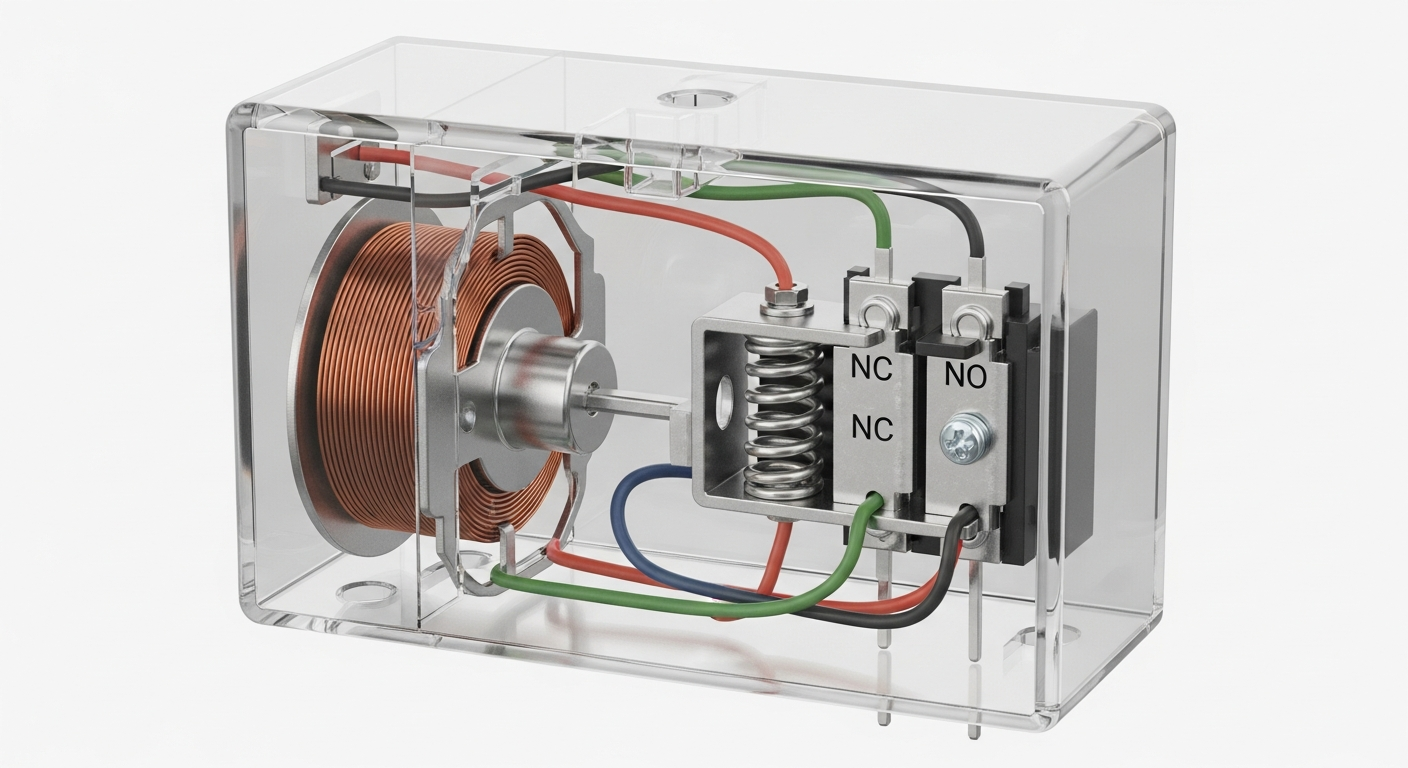
An SPDT relay includes a coil, armature, spring, and contact set arranged to create two output states.
Coil Activation, Magnetic Movement, and Contact Mechanics
The coil creates a magnetic field once energized. This pulls the armature, forcing the movable contact to switch from NC to NO. A spring resets the contact to NC when the coil turns off. The housing provides insulation and mechanical protection, while contact plating enhances conductivity and reduces wear.
In manufacturing practice, incorrect placement or excessive heat during soldering can deform relay housing or weaken coil insulation. Factories with DIP soldering expertise adjust wave-solder profiles, confirm hole sizes, and ensure thermal relief patterns. This supports strong mechanical bonding and consistent contact performance across industrial and consumer applications.
Where are SPDT relays commonly used?
Choosing the wrong relay type leads to noise, voltage drop, or mechanical stress.
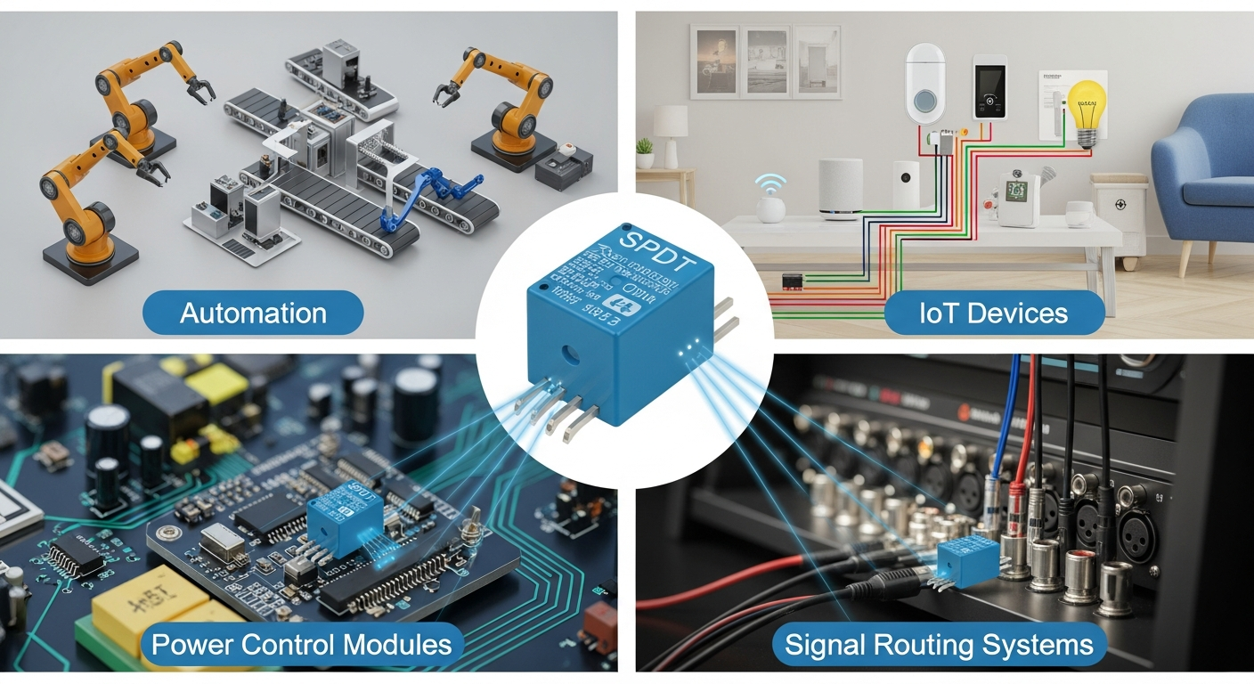
SPDT relays appear in automation, IoT devices, power control modules, and signal-routing systems.
Industrial, Automotive, and Consumer-Electronics Uses
SPDT relays control motors, solenoids, pumps, HVAC modules, lighting paths, and safety interlocks. In IoT and home-automation boards, they allow switching between active and standby modes. In automotive designs, they handle direction changes, load protection, and accessory management.
Engineering-oriented factories review current ratings, coil drive circuits, and surge-protection requirements. Combined PCB fabrication and SMT/DIP assembly ensure correct pad design, safe creepage distance, and reliable contact separation for high-voltage switching. This helps avoid certification issues in UL, CE, or automotive compliance testing.
How does an SPDT relay affect PCB design?
Poor routing or pad layout can cause arcing, heating, or electromagnetic noise.
SPDT relays require proper trace width, isolation spacing, and thermal planning on the PCB.
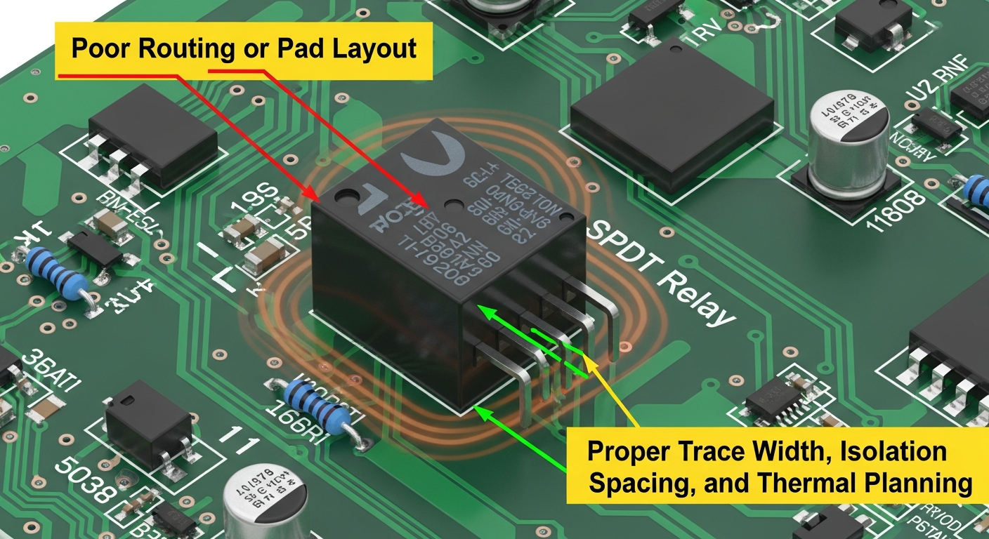
Clearance, Trace Sizing, and Isolation
High-current paths need wider copper and reinforced pads. Coil and load sections should be separated to minimize noise coupling. Mechanical relays also require cutouts or slots for insulation when switching AC mains or inductive loads. Flyback diodes protect driver circuits when switching DC coils.
In factory workflows, CAM engineers validate creepage and clearance for AC/DC loads, confirm hole diameters for relay pins, and check copper balance to avoid warpage. SMT/DIP assembly teams verify alignment and inspect solder joints with AOI and functional testing. This ensures stable switching behavior across all production quantities.
What factors determine SPDT relay reliability?
Contact wear, coil stress, and mechanical fatigue reduce relay life.
Reliability depends on contact rating, coil drive conditions, environmental stress, and load type.
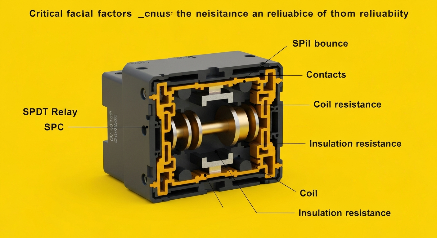
Contact Quality, Switching Frequency, and Load Dynamics
Inductive loads create voltage spikes that damage contacts. High-frequency switching increases mechanical wear. Temperature, humidity, vibration, and contamination also influence longevity. Proper snubber, varistor, or diode protection extends relay life dramatically.
Factories with integrated engineering, procurement, and testing validate relay specs, propose alternate part numbers when needed, and test under real load conditions. Functional testing and long-cycle stress checks ensure the relay works reliably in industrial, IoT, and consumer environments before moving to mass production.
Conclusion
An SPDT relay is a versatile switching component that routes one input between two output paths, supporting power management, logic control, and multi-state system design. Proper selection, PCB layout, and protective circuitry ensure stable long-term performance. With engineering-guided manufacturing, BOM optimization, and complete SMT/DIP assembly and testing, relay-based products achieve consistent quality from early prototypes to large-scale production. This strengthens system reliability, reduces field failures, and supports long-term success in industrial, automotive, automation, and IoT applications.
