
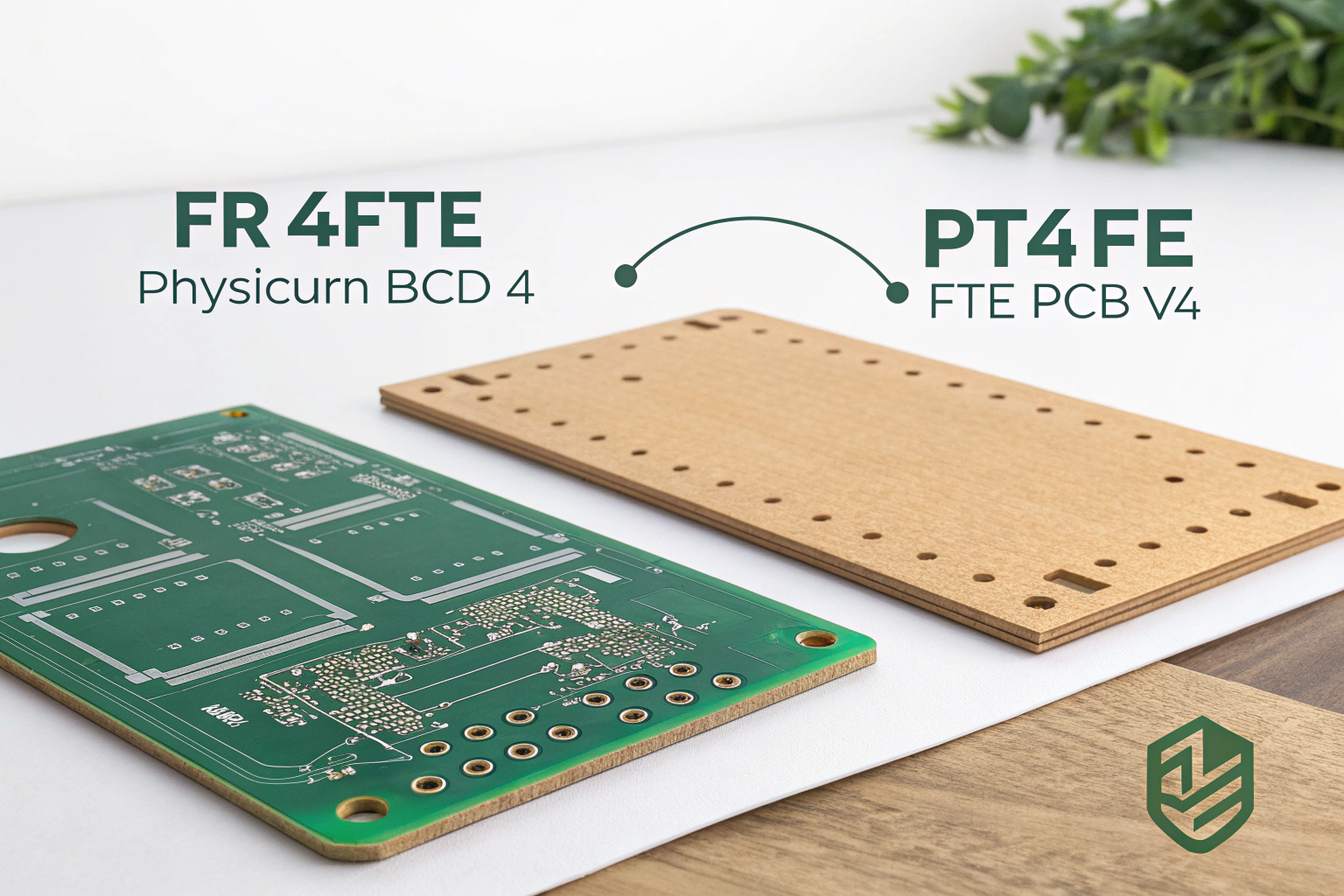
FR4 and PTFE are two widely used PCB substrate materials with very different electrical, thermal, and manufacturing characteristics. FR4 is a glass-fiber epoxy laminate designed for general-purpose electronics, while PTFE is a high-performance material optimized for high-frequency and microwave applications.
From a manufacturing perspective, the difference between FR4 and PTFE goes far beyond material cost. It affects factory equipment selection, process control, workshop environment, and long-term product reliability.
What are FR4 and PTFE made of?
FR4 is composed of woven fiberglass cloth impregnated with epoxy resin. The material is flame-retardant and mechanically rigid, making it suitable for most rigid PCB applications.
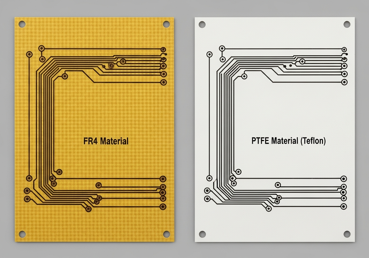
PTFE, commonly known by its chemical name polytetrafluoroethylene, is a fluoropolymer material. In PCB applications, PTFE is often reinforced with glass fiber or ceramic fillers to improve mechanical strength.
In factory production, FR4 behaves like a stable composite material, while PTFE behaves more like a soft, thermoplastic-based laminate. This fundamental difference drives most process and performance distinctions.
How do electrical properties differ between FR4 and PTFE?
Electrical performance is the primary reason PTFE is chosen over FR4.
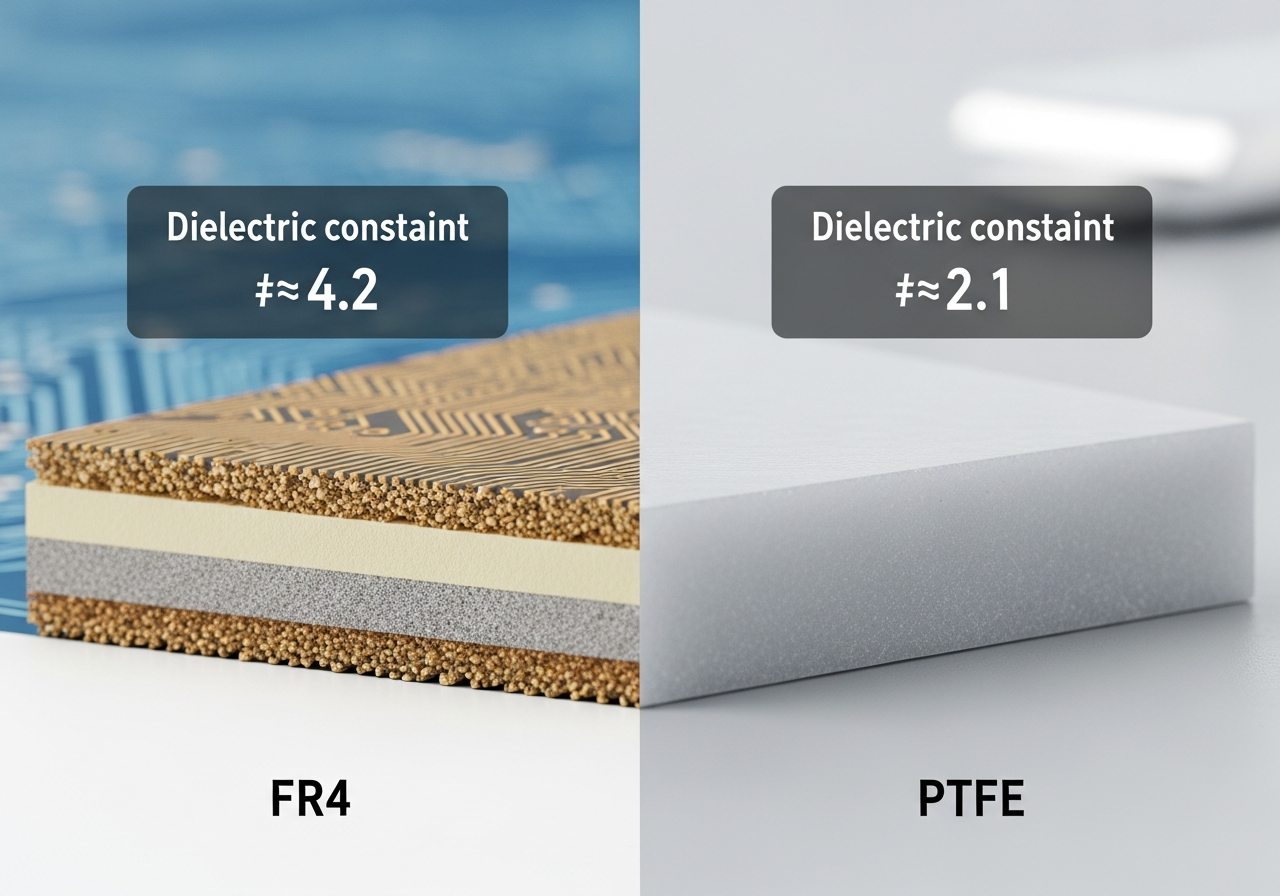
FR4 has a dielectric constant typically around 4.2–4.8, which varies with frequency. It also has higher dielectric loss, making it less suitable for high-frequency signal transmission.
PTFE has a much lower dielectric constant, usually around 2.1–2.6, and extremely low dielectric loss. This allows signals to travel with less attenuation and distortion at high frequencies.
In manufacturing-oriented design, this means FR4 is suitable for low- to mid-frequency circuits, while PTFE is preferred for RF, microwave, and high-speed communication boards.
How do FR4 and PTFE differ in thermal behavior?
Thermal characteristics significantly impact both fabrication and assembly.
FR4 has moderate thermal resistance and a defined glass transition temperature (Tg). Once Tg is exceeded, mechanical stability decreases, but within limits FR4 performs well during standard soldering processes.
PTFE does not have a traditional Tg like epoxy materials. It has excellent thermal stability but a high coefficient of thermal expansion, especially in the Z-axis.
In factory workshops, PTFE requires stricter thermal profile control during lamination and soldering. Improper handling can lead to dimensional instability or via reliability issues.
How does manufacturing process differ for FR4 and PTFE?
FR4 is highly compatible with standard PCB fabrication processes.
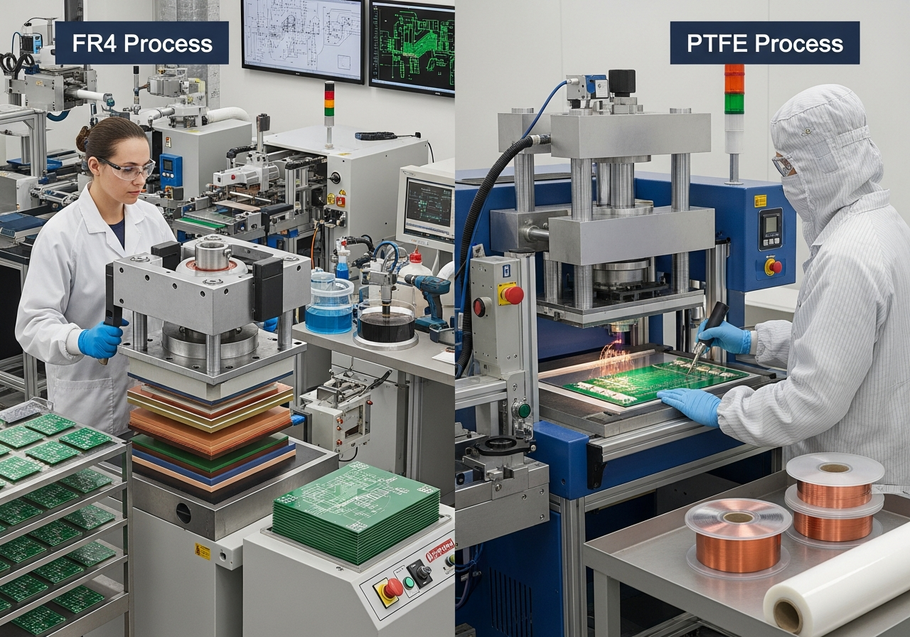
Drilling, plating, lamination, and etching parameters for FR4 are well-established. Tool wear is predictable, and copper adhesion is strong. This allows high yield and stable mass production.
PTFE requires specialized manufacturing techniques. Drilling must be slower to prevent material smear. Plasma treatment is often required to improve copper adhesion. Lamination profiles are more complex and sensitive.
Factories producing PTFE boards typically maintain dedicated process lines and trained operators. Process windows are narrower, and material handling is more demanding.
How do cost and yield compare between FR4 and PTFE?
Cost differences between FR4 and PTFE are significant.
FR4 is widely available and cost-effective, with high manufacturing yield and low scrap rates. It is suitable for both prototypes and volume production.
PTFE materials are significantly more expensive. Manufacturing yield is lower due to tighter process control and higher sensitivity to variation.
From a factory management standpoint, PTFE production requires careful scheduling, strict quality monitoring, and higher technical involvement to maintain acceptable yields.
Where are FR4 and PTFE typically used?
FR4 is used in a broad range of electronic products, including industrial control boards, power electronics, consumer devices, and general communication equipment.
PTFE is primarily used in high-frequency applications such as RF modules, microwave circuits, antennas, radar systems, and advanced communication infrastructure.
Material selection is driven by electrical requirements rather than structural similarity. In many designs, FR4 and PTFE may even coexist in hybrid stack-ups.
How do factory workshops manage FR4 and PTFE differently?
Workshop management differs significantly between the two materials.
FR4 materials are stored and processed under standard temperature and humidity controls. Production lines are optimized for efficiency and volume.
PTFE materials require controlled storage, careful handling, and dedicated lamination and drilling setups. Process records and inspection frequency are typically increased to ensure consistency.
This separation ensures that PTFE’s unique properties are fully respected without compromising production stability.
Conclusion
FR4 and PTFE serve very different roles in PCB manufacturing. FR4 offers a balanced combination of electrical performance, mechanical strength, cost efficiency, and manufacturing stability, making it the default choice for most rigid PCBs.
PTFE delivers superior high-frequency electrical performance but demands specialized materials, tighter process control, and higher manufacturing expertise. When produced in a capable factory environment with appropriate equipment and discipline, PTFE PCBs provide unmatched signal integrity for advanced RF and microwave applications.
