The main PCB board provides structural support, electrical connections, and functional coordination for all components inside an electronic device.

A clear understanding of a main PCB’s role helps engineering teams design stable systems, reduce assembly errors, and prepare for smooth prototype-to-production transitions.
Why is the main PCB considered the core of an electronic system?
Many system failures come from poorly designed or unstable mainboards that cannot support power, signals, or modules correctly.
The main PCB connects, powers, and coordinates every subsystem, acting as the central platform for a device’s functionality.
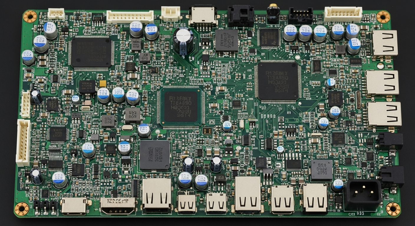
Central Control, Connectivity, and Structural Support
The main PCB holds microcontrollers, processors, memories, sensors, and communication chips. It distributes power, manages data traffic, and ensures mechanical stability. Without a well-designed mainboard, devices suffer from unstable voltage, weak signal routing, or component misalignment.
In B2B hardware development, incomplete stackups, poor grounding, or mismatched footprints often delay prototypes. Engineering-focused factories review DFM issues, optimize trace paths, confirm BOM feasibility, and align layout rules with SMT capabilities. This reduces redesign cycles and improves first-round success for small-batch and mass-production runs.
How does the main PCB manage power distribution?
Unstable power lines cause noise, heat issues, and random resets during testing or field use.
The main PCB delivers regulated, stable power to each subsystem through controlled routing and filtering.
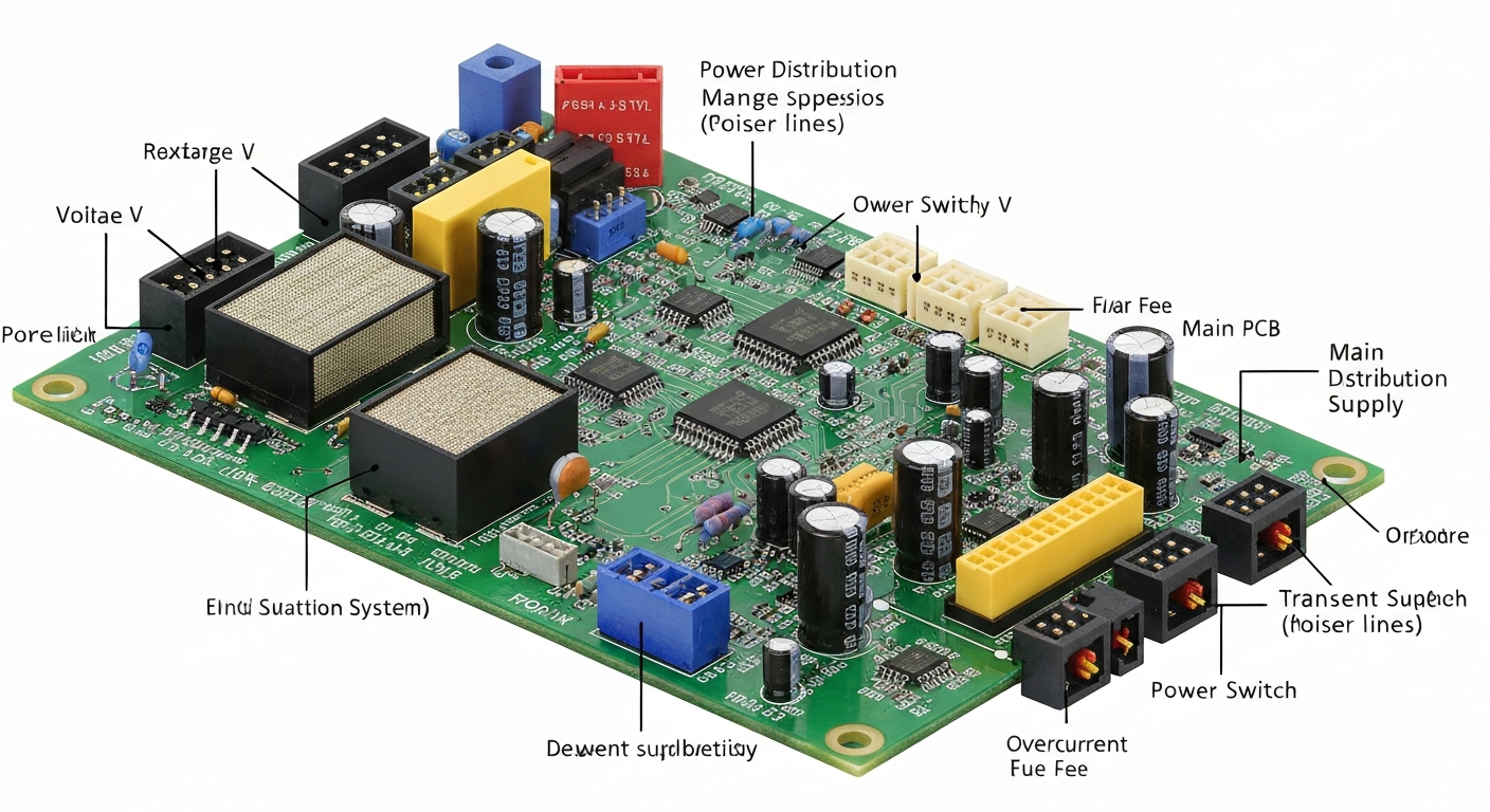
Voltage Regulation, Filtering, and Load Stability
Power sections on the main PCB control input voltage, step-down conversion, decoupling, and noise filtering. Wide copper pours, short return paths, and well-placed regulators ensure consistent delivery to processors, drivers, and sensors. Heat-generating components rely on thermal vias and copper zones for safe operation.
In commercial hardware builds, weak power networks frequently show up during AOI, ICT, or FCT tests. Manufacturing teams with OEM/ODM experience verify copper thickness, simulate current paths, and optimize thermal structures. With integrated PCB and SMT production, power-related risks are handled before scaling to larger batches.
What role does the main PCB play in signal integrity?
Poor routing, insufficient grounding, or improper impedance often causes data errors, EMI, or flaky communication.
The main PCB preserves clean, stable signals across digital, analog, and RF paths.
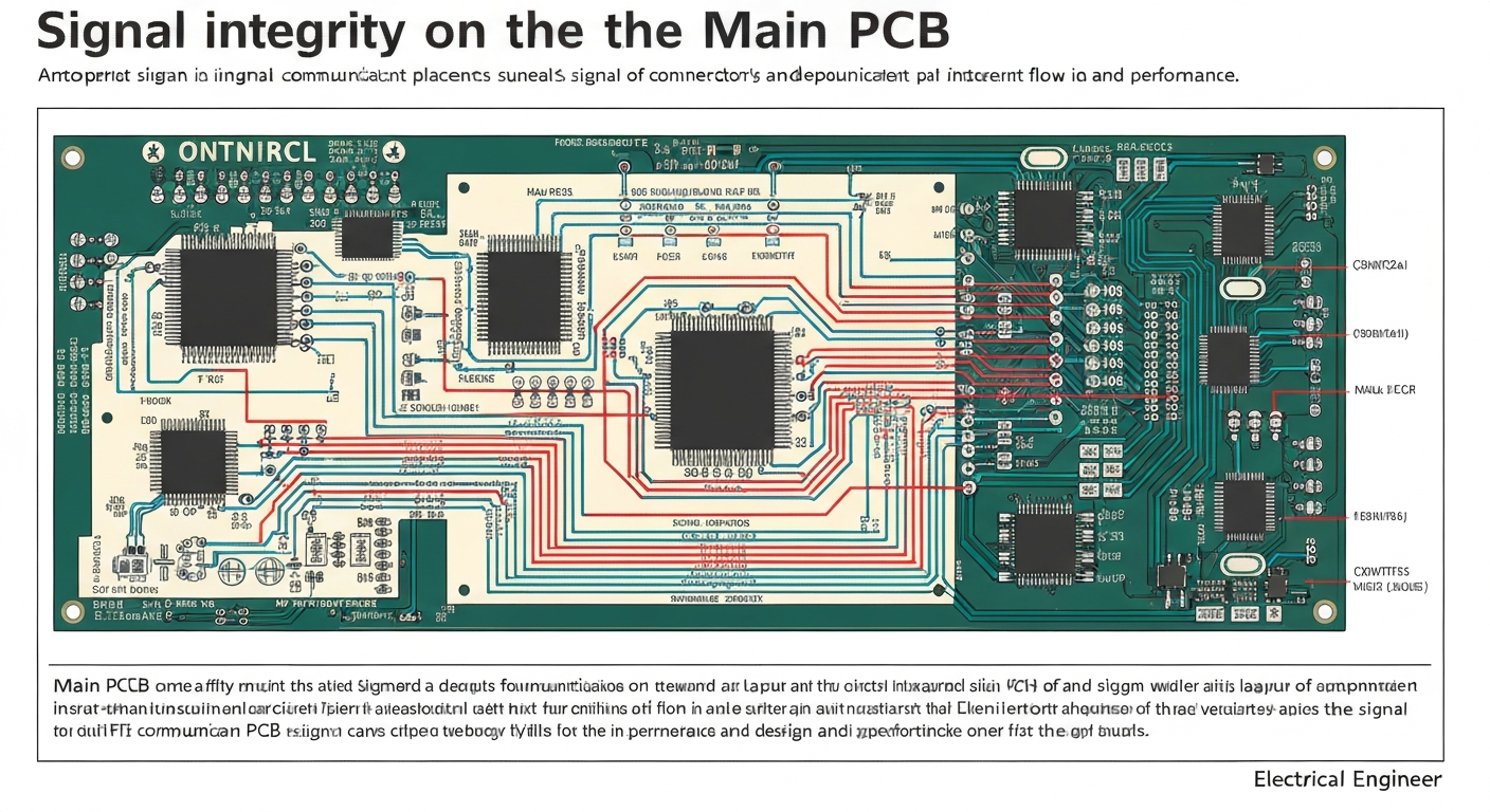
Controlled Impedance, Grounding Strategy, and Layer Design
High-speed traces depend on controlled impedance and balanced routing. Differential pairs, shielding grounds, stitching vias, and top-to-bottom layer transitions shape how well signals travel. Analog sections require isolation from switching noise, while RF areas need careful clearance and matching.
Factories combining CAM analysis, stackup design, and SMT assembly check routing tolerance, via structures, and component placement. This ensures that the main PCB supports stable communication, avoids late-stage noise problems, and maintains consistent performance across multiple production batches.
How does the main PCB ensure mechanical and assembly reliability?
Misaligned footprints or weak board shapes often cause assembly defects, warpage, or mechanical damage.
The main PCB gives the device structural integrity, supports connectors, and aligns components for automated assembly.
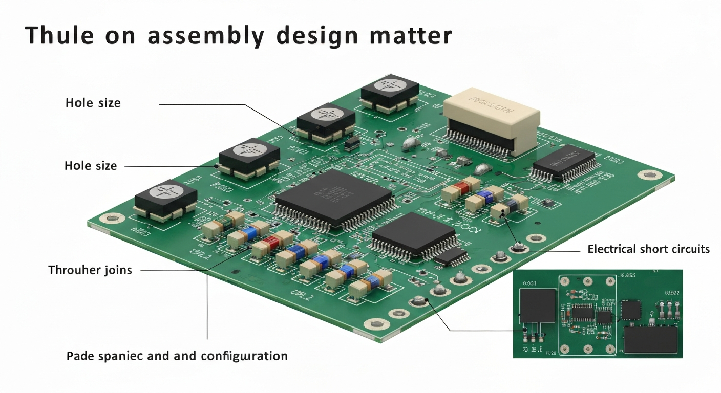
Mounting Points, Connectors, and Panelization
The board defines mounting holes, connector locations, and reinforcement areas. Mechanical outlines match enclosure requirements, making sure the product assembles smoothly. Panelization rules ensure correct spacing for pick-and-place machines, reflow ovens, and cutting processes.
Manufacturing teams identify risks such as connector stress, insufficient copper balance, or irregular board outlines. With real factory data and IPC-A-610 standards, adjustments are made before fabrication begins. This leads to fewer assembly problems, stronger structural endurance, and higher production yield.
How does the main PCB coordinate the entire electronic system?
When subsystems fail to communicate or synchronize, the whole product becomes unreliable.
The main PCB integrates control logic, communication interfaces, and timing functions for the entire device.
Communication Buses, Timing, and Module Integration
The mainboard hosts buses like I²C, SPI, UART, CAN, or Ethernet. It links sensors, displays, wireless modules, and power units into a unified system. Clock lines, reset circuits, and firmware interfaces support predictable operation and consistent startup behavior.
In advanced hardware builds, integration mistakes create cascading failures across subsystems. Factories with design-for-manufacturing workflows validate pin mapping, firmware headers, interface spacing, and grounding consistency. This ensures clean interaction between modules and smooth scalability from prototype to mass production.
Conclusion
The main PCB is the foundation of every modern electronic device, supporting power delivery, signal routing, mechanical structure, and full system coordination. A well-designed mainboard ensures stability, reliability, and long-term performance. When combined with manufacturing partners offering PCB fabrication, SMT assembly, BOM optimization, and complete testing, mainboard production becomes predictable and repeatable. This improves prototype efficiency, reduces redesign cycles, and supports long-term growth for industrial, IoT, and consumer electronics across global markets.

