
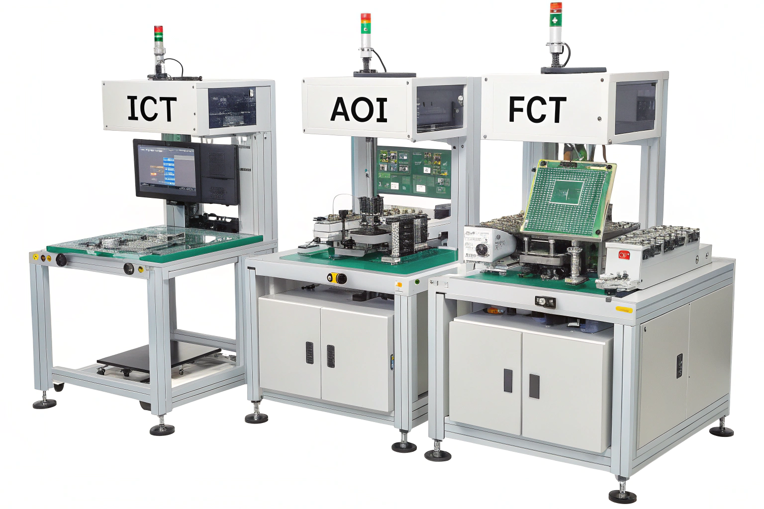
When I support customers during pilot production, one key tool that always comes up is ICT. Many teams are familiar with AOI or flying probe, but ICT is the test that reveals deep electrical issues hidden inside assembled boards.
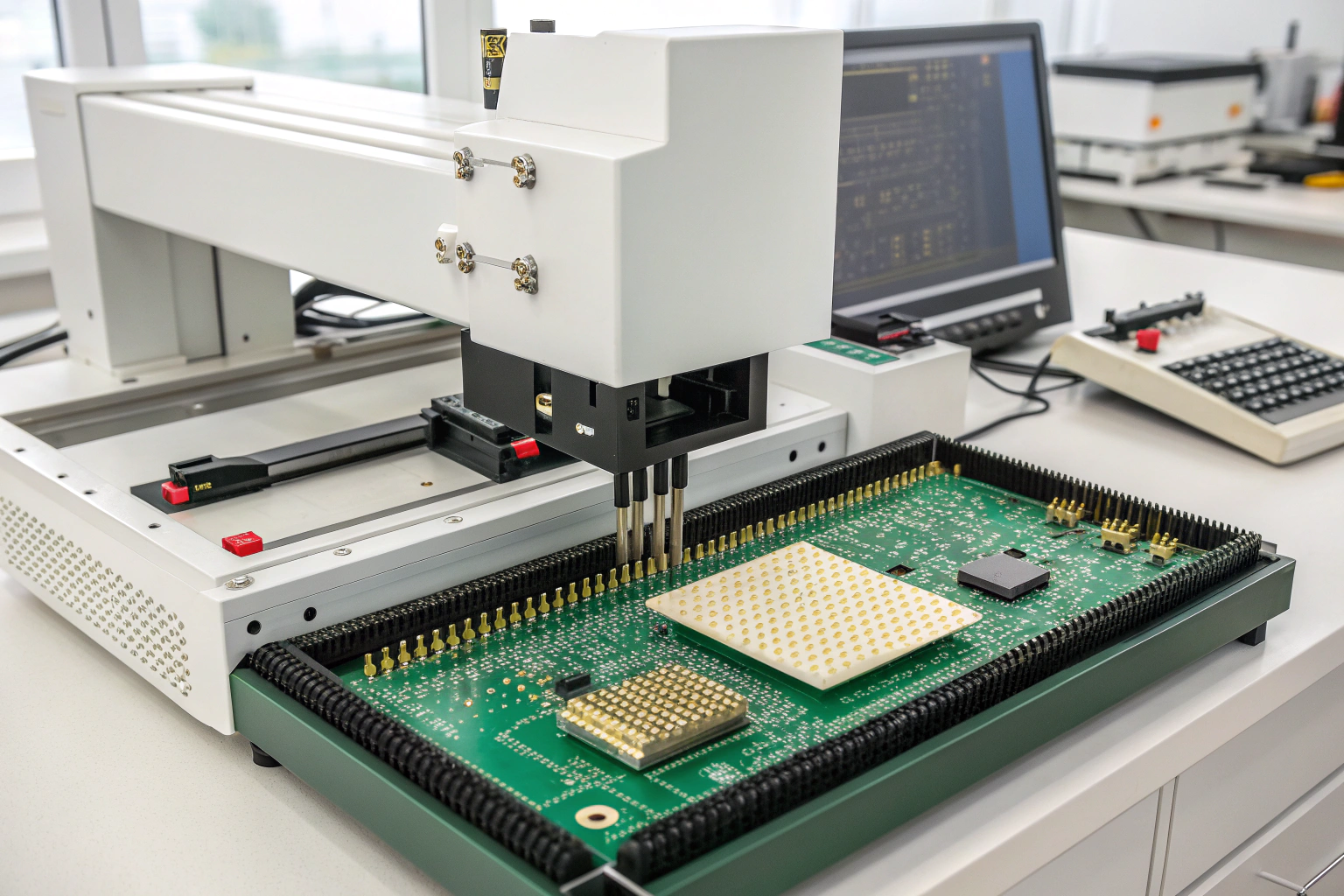
ICT (In-Circuit Test) is a fixture-based electrical test that checks components, connections, and circuits on a PCB by probing test points with hundreds of pins simultaneously.
Understanding ICT helps you decide when to use it, how it improves yield, and how to design your PCB to support this powerful manufacturing test method.
What does ICT testing do in PCB assembly?
ICT looks inside your board—literally. It examines every node, component, and connection individually, something no visual inspection can do.
ICT tests individual components and nets on a PCB using a fixed bed-of-nails fixture to measure resistance, capacitance, shorts, opens, and device programming.
How ICT works and why it matters
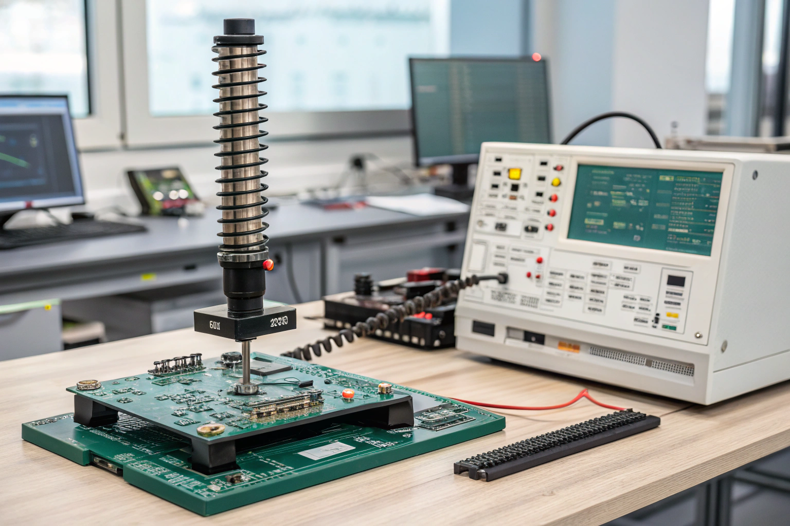
ICT uses a large test fixture filled with spring-loaded pins. These pins contact specific test pads on the PCB and perform automated measurements.
ICT can check:
| ICT Function | What It Detects |
|---|---|
| Continuity | Broken traces, open circuits |
| Shorts | Copper bridges, solder faults |
| Component value checks | Wrong R, C, L values |
| Polarity checks | Wrong diode, capacitor orientation |
| IC presence and ID | Missing or wrong chips |
| Programming / flashing | MCU, EEPROM, or CPLD programming |
| Power line verification | VBUS, 3V3, 5V rails |
| Current leakage | Wrong or damaged components |
When I manage production runs, ICT often catches issues like swapped resistors, incorrect IC rotation, missing pull-ups, weak solder joints, or wrong component values—problems that might otherwise go into finished products unnoticed.
How does the ICT test actually work?
Many engineers hear about ICT but don’t fully understand the process. Knowing how it works helps you design better testable PCBs.
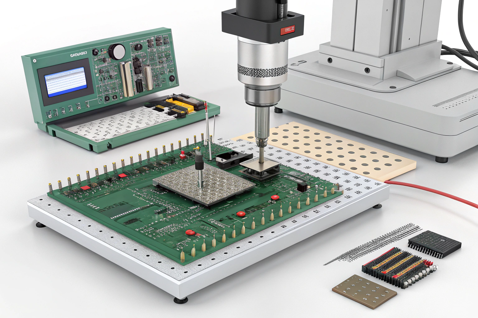
ICT uses a dedicated fixture with spring-loaded pins, automated test scripts, and controlled measurement instruments to check circuits and components directly on the assembled board.
A deeper look at the ICT test workflow
1. A custom test fixture is built
Each product requires a unique “bed-of-nails” fixture.
It contains hundreds of pogo pins aligned to your PCB’s test pads.
The factory uses your:
- Gerber
- Centroid
- Netlist
- BOM
to design the fixture.
2. Probes contact all test pads simultaneously
This is the main difference from flying probe.
- Flying probe uses 2–4 probes
- ICT uses 100–2000 probes at once
This makes ICT incredibly fast and thorough.
3. Automated electrical measurements begin
ICT measures:
- resistances
- capacitances
- diode forward voltage
- transistor behavior
- IC identification
- open/short detection
- voltage rails
- signal integrity on key nodes
It tests components in place (in-circuit).
This provides deep verification of assembly quality.
4. Optional MCU programming and functional tests
Many factories combine:
- MCU flashing
- EEPROM writing
- Basic power-up test
So the device leaves the ICT station fully programmed and verified.
5. ICT generates a complete pass/fail report
After test completion, the system outputs:
- fault location
- component reference (e.g., R45, D7, U2)
- type of failure (wrong value, open, short)
- measurement value
This helps engineers diagnose issues immediately.
I’ve seen ICT reduce debugging time by 70% on complex boards.
Why choose ICT over other tests like AOI or flying probe?
Customers often ask me when ICT makes sense and when it doesn’t. Each test plays a different role.
ICT is best for medium-to-high volume production because it gives fast, accurate, and detailed electrical testing using custom fixtures.
Why ICT is valuable in real manufacturing
1. Extremely fast testing
ICT can test a full board in seconds, while flying probe may take minutes.
2. Very high coverage
ICT checks:
- component values
- shorts/opens
- orientation
- in-circuit behavior
- programming
Flying probe can’t measure everything, especially when components interact.
3. Ideal for stable, repeated production
Once the fixture is built, ICT becomes highly cost-efficient.
4. Perfect for complex or dense boards
Boards with BGAs, QFNs, and fine-pitch ICs benefit because ICT can detect faults hidden under the package.
5. High accuracy and repeatability
It removes human subjectivity and delivers consistent results.
At my factory, we recommend ICT for boards with:
- stable design
- medium to large batch orders
- many passive components
- high reliability requirements
- any product entering long-term mass production
ICT becomes a long-term cost-saving tool because it eliminates defect escape in large quantities.
Conclusion
ICT is a powerful in-circuit testing method that uses a custom fixture and automated measurements to verify components, nets, and electrical behavior on a PCB. It provides fast, accurate, and high-coverage testing that is ideal for medium and high-volume production. With proper schematic planning, clear test points, and a well-prepared layout, ICT ensures stable product performance and gives your design the reliability needed for long-term success.
