
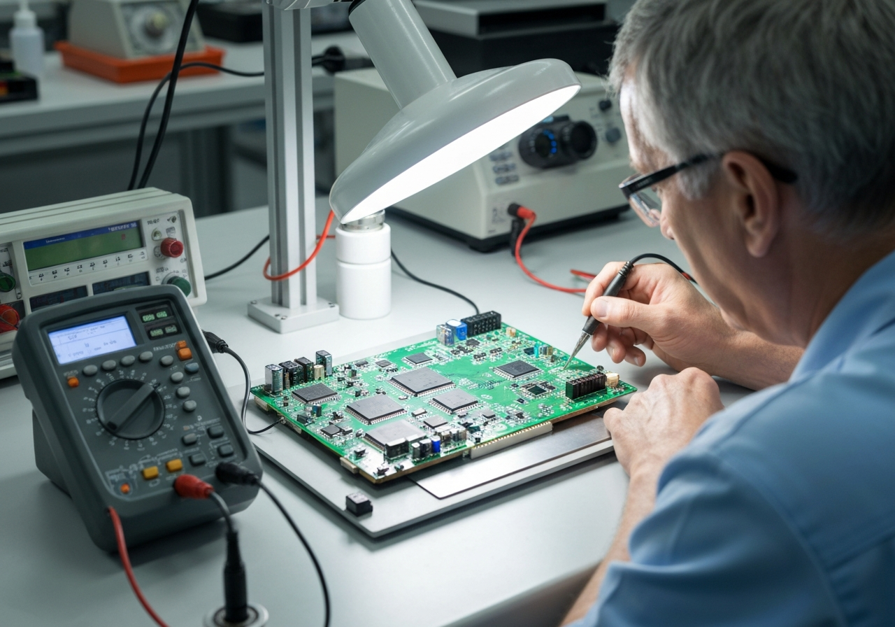
The most versatile tool to troubleshoot a PCB is the digital multimeter. It combines voltage measurement, current measurement, resistance testing, and continuity checking in one instrument, making it indispensable for diagnosing most PCB faults from early inspection to failure analysis.
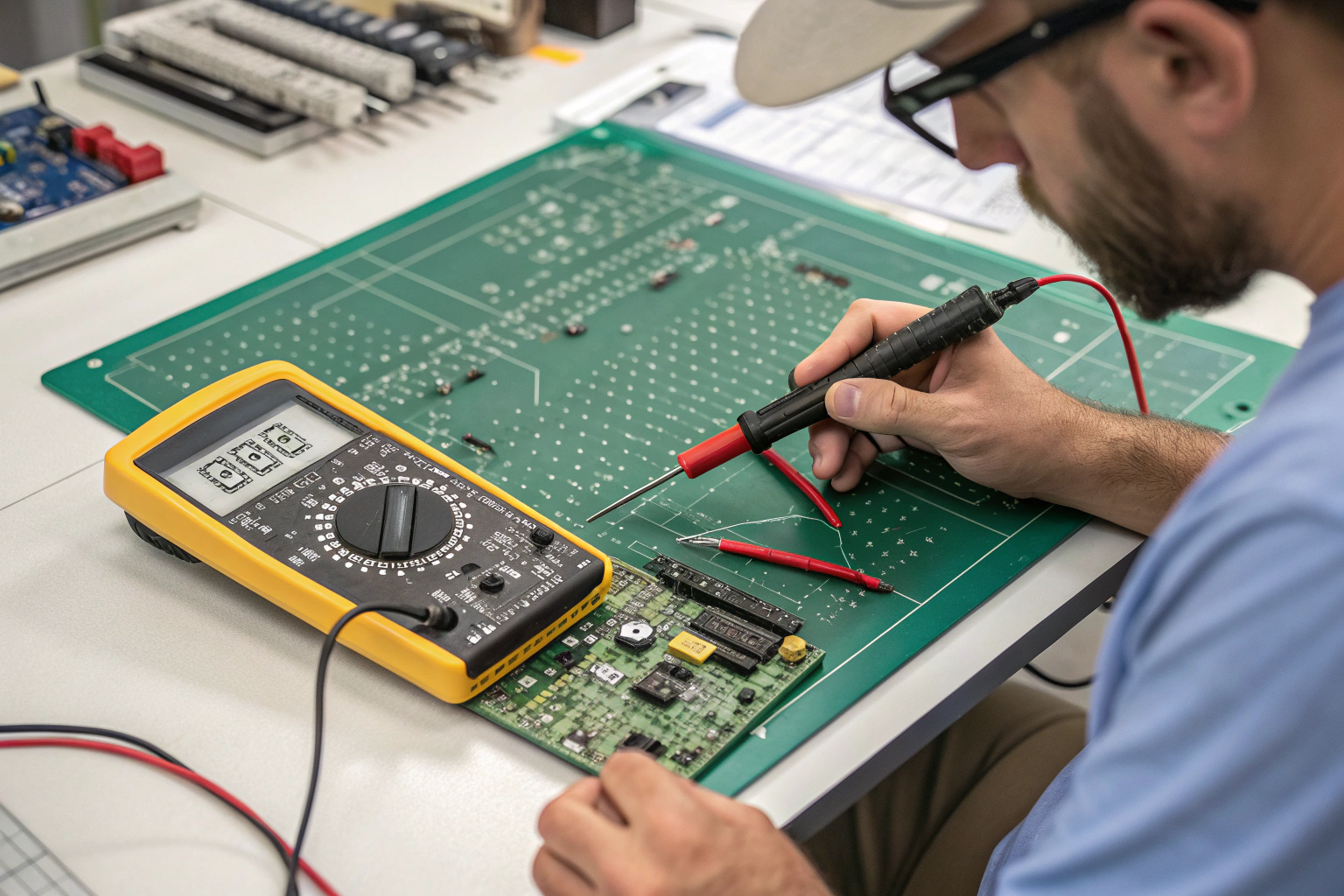
In electronics manufacturing and assembly, the multimeter is not a secondary tool. It is the foundation of PCB troubleshooting, used before advanced equipment such as oscilloscopes or X-ray systems.
A well-used multimeter often reveals the root cause of a PCB problem faster than complex test systems when applied with structured methods.
Why the Digital Multimeter Is Central to PCB Troubleshooting?
Versatility defines troubleshooting efficiency.
One tool answers many questions.
A digital multimeter supports multiple diagnostic tasks without powering the board or altering its state. It allows engineers and technicians to verify whether the PCB is electrically sound before deeper testing begins.
Key capabilities include:
- Continuity testing for trace integrity
- Resistance measurement for degraded paths
- Voltage verification during power-up
- Current monitoring for abnormal load
These functions cover the majority of PCB failure modes, especially those related to solder joints, broken traces, shorts, and power distribution issues.
In manufacturing workshops, multimeters are used at incoming inspection, in-process checks, rework validation, and final failure analysis. Their value comes from speed, accuracy, and low risk when used correctly.
How Continuity Testing Solves Most PCB Faults?
Most PCB failures are simple in nature.
Continuity testing exposes them quickly.
Continuity mode verifies whether two points on a PCB are electrically connected as intended. This is the fastest way to detect:
- Broken traces
- Lifted pads
- Cracked vias
- Poor solder joints
For short-circuit detection, continuity testing reveals unintended connections between power, ground, or adjacent signal paths.
In factory environments, continuity testing is often the first response to functional test failure. It prevents unnecessary power application to damaged boards and helps isolate defects before rework begins.
Even on multilayer boards, continuity testing confirms vertical connectivity through vias and component leads, which are common failure points during thermal stress or mechanical handling.
Why Voltage Measurement Is Critical During Power-Up?
Power issues cause the highest damage risk.
Voltage checks control that risk.
Voltage measurement confirms whether power rails behave as designed. Incorrect voltage levels often point to regulator failure, short circuits, or incorrect component placement.
During controlled power-up, voltage measurement helps identify:
- Missing supply rails
- Undervoltage or overvoltage conditions
- Incorrect polarity connections
In manufacturing workshops, power-up is always paired with multimeter monitoring. Current-limited supplies are used, and voltage readings are compared against design specifications.
This approach prevents secondary damage and allows faults to be corrected early, before components or PCB materials are permanently affected.
How Resistance and Current Measurement Reveal Hidden Defects?
Not all PCB faults are binary.
Some degrade gradually.
Resistance measurement helps identify partially damaged traces, corroded copper, or stressed solder joints. A trace may still show continuity but exhibit abnormally high resistance.
Current measurement highlights:
- Excessive load conditions
- Leakage paths
- Shorted components
In production environments, abnormal current draw during early power-up is treated as a serious warning sign. Multimeters help quantify this behavior before catastrophic failure occurs.
These measurements are especially valuable for power electronics, control boards, and dense PCBs where heat and stress accelerate degradation.
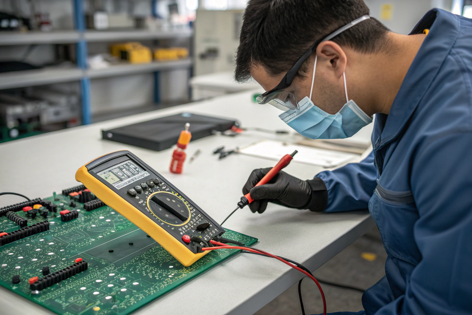
How the Multimeter Fits into Factory Workshop Processes?
Troubleshooting tools must match production reality.
The multimeter fits every stage.

In a professional factory workshop, multimeters are integrated into structured workflows:
- Incoming PCB verification
- SMT and DIP process checks
- Rework and repair validation
- Final failure analysis
Each workstation is ESD-protected and equipped with calibrated multimeters. Measurements are recorded and linked to serial numbers for traceability.
When repeated issues appear, multimeter data supports root cause analysis. It helps determine whether the failure originated from PCB fabrication, assembly parameters, material quality, or handling.
Advanced tools are used later, but the multimeter remains the first and most frequently applied diagnostic instrument.
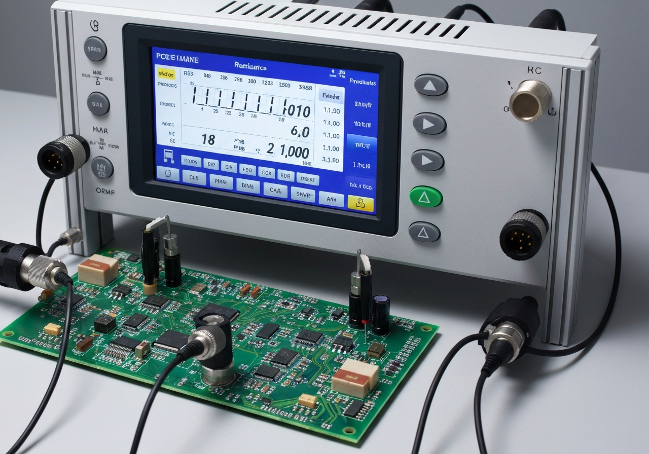
Why Other Tools Cannot Fully Replace a Multimeter?
Advanced tools provide depth, not coverage.
Versatility still matters most.
Oscilloscopes analyze signal behavior. X-ray systems inspect hidden solder joints. AOI checks visual quality. Each tool serves a specific purpose.
However, none of these tools replace the multimeter’s ability to:
- Verify basic electrical integrity
- Diagnose without powering the board
- Support fast, low-risk decisions
In manufacturing, troubleshooting efficiency depends on narrowing problems quickly. The multimeter does this better than any single advanced instrument.
Conclusion
The digital multimeter is the most versatile tool for PCB troubleshooting because it addresses the most common and critical failure modes with speed, accuracy, and minimal risk. Its ability to test continuity, resistance, voltage, and current makes it effective from early inspection through final failure analysis. In professional manufacturing workshops, the multimeter is embedded into every stage of process control, rework validation, and quality assurance. While advanced diagnostic equipment adds depth, the multimeter provides the broad foundation needed to identify problems efficiently and protect product reliability. Reliable PCB troubleshooting does not start with complexity. It starts with the right basic tool, applied with discipline and process awareness.
