
Understanding the Basic Components of Printed Circuit Boards (PCBs): A Beginner’s Guide and Practical Tips
If you are new to the electrical and electronics industry, understanding the schematic of printed circuit board (PCB) components may seem complex and daunting at first glance. This feeling is entirely normal, as even some experienced professionals find it challenging to delve into these details. Generally, a circuit board consists of at least 15 basic components, each with its unique function and purpose.
Mastering the knowledge of these basic components not only helps you identify faults but also enhances your understanding of the PCB’s performance. For example, resistors are used to limit current flow, capacitors store and release electrical energy, while integrated circuits are key to achieving complex functions. Additionally, understanding the interconnections between components and the signal transmission paths allows you to be more proficient in maintaining and designing circuits.
In the following sections, we will discuss these basic components in detail, including their characteristics, applications, and importance in various contexts. Understanding these components’ functions will provide you with a solid foundation, enabling you to build and analyze circuit boards more effectively in practical applications. This knowledge not only improves your work efficiency but also aids in your rapid growth within the electronics industry. Therefore, whether you are learning PCB design or aiming to enhance your troubleshooting skills, delving into these components is an essential step.
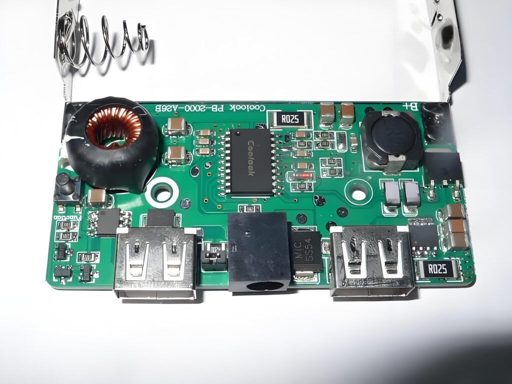
A Guide to Identifying Surface Mount Components on Circuit Boards
SMD components, or Surface Mount Devices, are electronic parts soldered onto circuit boards using surface mount technology (SMT). Due to their compact size and efficient performance, these components are widely used in modern electronic products.
Depending on their layout and type, SMD components can be utilized in various applications. Industry experts have established multiple size standards for these components to meet different design needs. The most common SMD components include chip resistors (R), network resistors (RA/RN), capacitors, transistors (Q), LEDs, and diodes.
The key to identifying these components lies in understanding their shape, size, and package type. SMD components typically have standardized appearances, making quick identification on circuit boards possible. As technology advances, the variety and complexity of SMD components continue to grow, making it essential to have a thorough understanding of these basic components for circuit board maintenance and troubleshooting.
Analyzing the Components of Circuit Boards
Many people often ask us questions about circuit board components and their functions. This is a worthwhile topic to explore, as understanding these components is fundamental to effectively using circuit boards. Insufficient knowledge about the composition of a circuit board can lead to improper use, negatively impacting its performance and reliability.
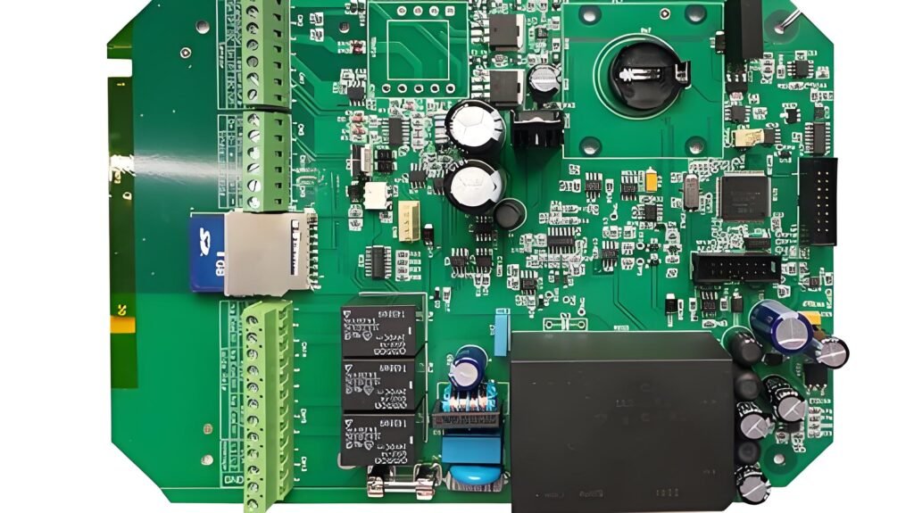
Circuit boards typically consist of various electronic components, each playing a crucial role in the overall circuit design. These components can be divided into active and passive components. Active components, such as transistors and integrated circuits, are responsible for amplifying and controlling current, while passive components, such as resistors and capacitors, primarily serve to store and release energy.
In addition to these basic components, circuit boards also include connectors, wires, and solder joints, all of which work together to ensure the stability and reliability of current flow. In the following sections, we will discuss the function, characteristics, and specific applications of each component in detail. This will help you make more accurate and effective judgments when designing, analyzing, and troubleshooting circuit boards. By gaining a deeper understanding of the various parts of a circuit board, you will be better equipped to grasp its working principles, enhancing your technical skills and practical experience.
Analysis of the Function and Structure of Resisors
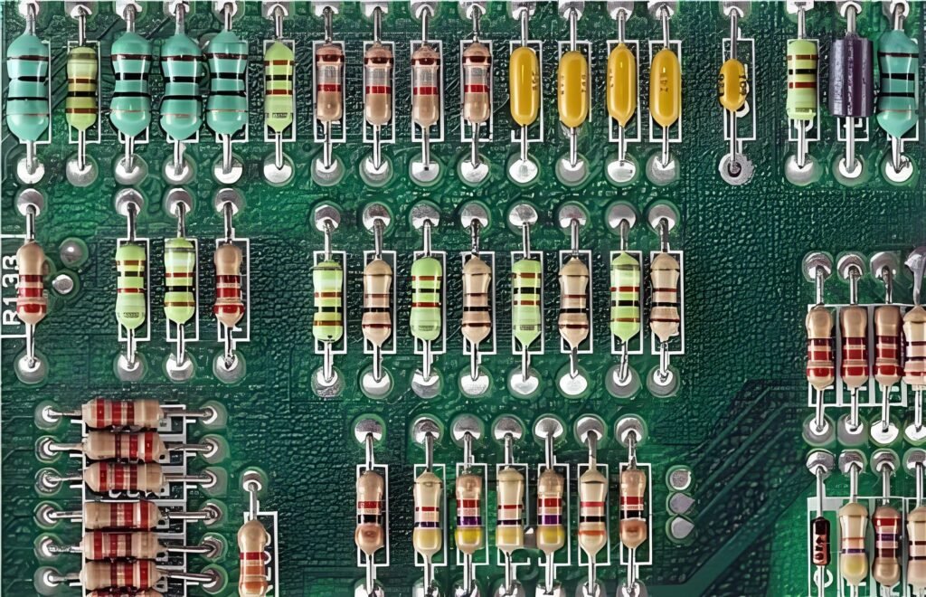
Resistors are indispensable basic components in all types of printed circuit boards (PCBs), used to control current flow. Their primary function is to limit the intensity of the current, ensuring the circuit operates normally. A resistor consists of two terminals, through which current can flow, creating the necessary voltage across the circuit.
Working Principle
The working principle of a resistor involves converting voltage into heat. This process occurs inside the resistor, where the material (commonly carbon film, metal film, or thick film) resists the current passing through, thereby converting electrical energy into thermal energy. This heat is dissipated by the resistor, effectively cooling the entire circuit board and preventing failures due to overheating.
Materials and Structure
The materials and structure of resistors directly influence their performance. Common resistor materials include:
- Carbon Film: Widely used in general circuits due to its low cost and ease of production.
- Metal Film: Offers higher precision and stability, suitable for stringent circuit designs.
- Thick Film: Often used in high-power circuits, capable of handling larger currents.
Resistors come in various types, including fixed resistors and variable resistors.
- Fixed Resistors have a constant resistance value.
- Variable Resistors (such as potentiometers) can adjust their resistance as needed to fit different circuit requirements.
Resistors also use color coding to indicate their resistance values, helping designers and engineers quickly identify and select the appropriate resistor.
Overall, resistors not only control current in the circuit but also play crucial roles in protecting other components, adjusting signal strength, and providing a stable operating environment. Understanding the characteristics of resistors and their applications in circuits will enhance the efficiency of circuit design and troubleshooting.
Analysis of the Function and Structure of Capacitors
Capacitors are important energy storage components on circuit boards, primarily used to temporarily store electrical energy. In printed circuit boards (PCBs), resistors control the charging process, while capacitors are responsible for storing these charges. You can think of a capacitor as a battery that charges and discharges rapidly.
Working Principle
A capacitor stores positive and negative charges through two conductive metal terminals. When the circuit board requires power, the capacitor quickly releases its temporarily stored charge. This characteristic allows capacitors to smooth out voltage fluctuations in the circuit and provide instant energy to meet sudden current demands.
Materials and Structure
Depending on the conductive metal plates used to manufacture them, various types of capacitors are available on the market. Common types of capacitors include:
- Radial Capacitors: Suitable for space-constrained applications and easy to install.
- Polyester Capacitors: Commonly used in high-frequency circuits, offering good stability and reliability.
- Ceramic Capacitors: Widely used in various circuits, known for their excellent high-frequency characteristics and temperature resistance.
The variety and characteristics of capacitors enable them to play significant roles in different circuits, particularly in applications such as filtering, coupling, decoupling, and timing. Understanding the properties of capacitors and their applications in circuits will help you enhance your circuit design and troubleshooting skills.
In summary, capacitors are not only energy storage components but also play a crucial role in stabilizing voltage and ensuring the normal operation of circuits. Mastering the working principles and applications of capacitors will improve your circuit design capabilities.
Analysis of the Function and Structure of Transformers
Transformers are key components in printed circuit boards (PCBs), primarily used to transfer electrical power from one source to another. They utilize electromagnetic induction technology for power conversion, enabling efficient voltage transformation between different levels to meet the power needs of various parts of the circuit board.
Working Principle
The basic principle of a transformer is to transfer electrical energy from the primary winding to the secondary winding through electromagnetic induction. During this process, the transformer can either step down or step up the voltage, ensuring that current is supplied to the circuit at an appropriate intensity. When current flows through the primary winding, it creates a magnetic field in the core, which induces current in the secondary winding.
Materials and Structure
PCBs typically feature transformers composed of several main parts:
- Windings: At least two separate windings (primary and secondary) are used for power input and output.
- Soft Iron Core: Enhances the strength of the magnetic field and provides a necessary magnetic path to improve the efficiency of the transformer.
The distinction between transformers and resistors lies in their functions. Resistors primarily limit current, while transformers regulate current flow by isolating it. This makes transformers vital in power distribution and current control.
Overall, transformers are not only tools for power transmission but also play a crucial role in the stability and safety of circuits. Understanding the working principles of transformers and their applications will help you optimize circuit design and enhance overall performance.
Analysis of the Function and Structure of Transistors
Transistors are essential basic components on printed circuit boards (PCBs) and are widely used in modern electronic devices. Their primary function is to amplify weak charges from power sources (such as batteries), ensuring that the PCB operates correctly.
Working Principle
The fundamental working principle of a transistor is to amplify signals by controlling the flow of current. On circuit boards, bipolar junction transistors (BJTs) are commonly seen, which consist of three terminals and three main regions for storing and amplifying charge. Depending on their structural characteristics, transistors are classified into two types: NPN and PNP.
Materials and Structure
The main components of a bipolar transistor include:
- Base: Acts as the control terminal of the transistor, determining the current flow through the other two terminals (collector and emitter).
- Collector: Responsible for collecting charge carriers regulated by the base and directing them into the circuit.
- Emitter: Used to emit or release charge, creating a flow of current.
Transistors contain both N-type and P-type regions, enabling effective signal amplification. The NPN transistor operates through the flow of electrons, while the PNP type relies primarily on the flow of holes.
In summary, the role of transistors in circuits extends beyond signal amplification; they also play crucial roles in switching control, signal processing, and other complex circuit functions. Understanding the working principles and applications of transistors will help optimize circuit design and enhance overall performance.
Analysis of the Function and Structure of Diodes
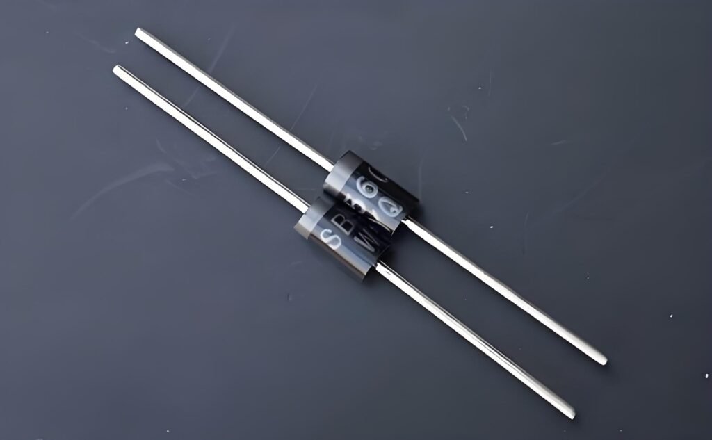
Diodes are important basic components in printed circuit boards (PCBs), primarily used to control the direction of current flow. Their working principle can be likened to a one-way street, allowing current to flow smoothly from one end to the other while blocking reverse flow.
Working Principle
A diode consists of two terminals: the anode and the cathode. The direction of current flow is from the anode (positive terminal) to the cathode (negative terminal). When the diode is in a conducting state, current can pass through it easily; however, under reverse voltage, the diode will block the current, ensuring that it flows in only one direction.
Materials and Structure
The basic structure of a diode includes:
- Anode: The positive terminal where current enters.
- Cathode: The negative terminal where current exits, usually marked by a line.
A common type of diode is the light-emitting diode (LED), which not only controls current but also emits light, making it widely used for display and indication purposes.
In summary, diodes play a crucial role in circuits. In addition to enabling unidirectional conductivity, they are also used for rectification, signal modulation, and circuit protection, among other applications. A deeper understanding of the working principles and characteristics of diodes will help improve circuit design and troubleshooting skills.
Analysis of the Role and Structure of Batteries in Circuit Boards
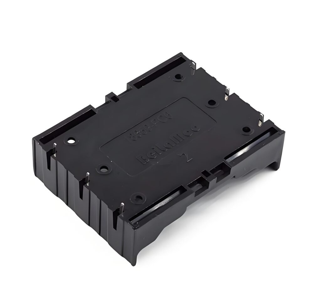
Batteries are essential components in printed circuit boards (PCBs), primarily used for energy storage and supply. They store energy through chemical reactions in their internal structure and convert it into electrical energy when needed for circuit operation.
Working Principle
The working principle of a battery is based on the conversion of chemical energy. The chemical reactions occurring within the battery generate electromotive force, creating a current that allows electrons to flow from the anode (positive terminal) to the cathode (negative terminal). This process not only provides the necessary power but also effectively supports the normal operation of the circuit. However, the current’s intensity is limited, so the electrical energy output by the battery often requires amplification to meet circuit demands. This task is typically performed by transistors to ensure stable power supply within the circuit.
Materials and Structure
The basic structure of a battery includes:
- Anode: The source of current, typically made of metal, which participates in the chemical reaction to release electrons.
- Cathode: The destination for the current, usually composed of a different material that accepts electrons.
- Electrolyte: Located between the anode and cathode, it allows ions to move within the battery, facilitating the chemical reactions.
In PCB applications, rechargeable batteries, such as lithium-ion and nickel-hydride batteries, are recommended. These batteries not only store and release energy efficiently but also offer a longer lifespan and lower environmental impact.
Batteries play a role in circuits beyond merely providing power; they can also influence the overall design and functionality of the circuit. Understanding the working principles of batteries and their applications in circuits can help you design circuits more effectively, optimize energy consumption, and address potential issues.
Analysis of the Role and Structure of Integrated Circuits in Circuit Boards
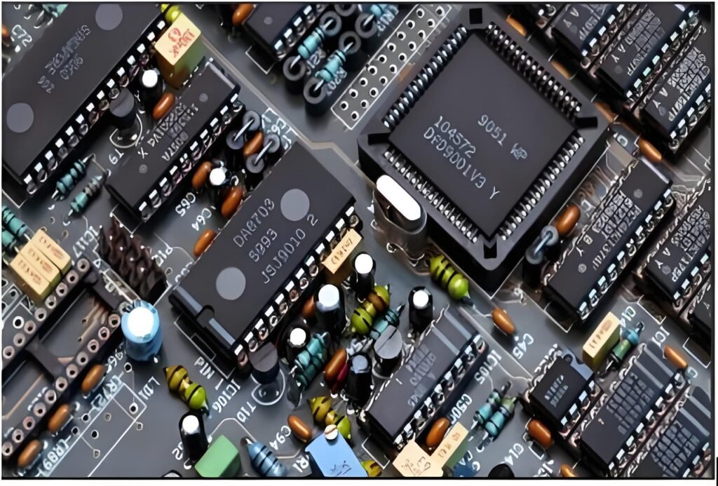
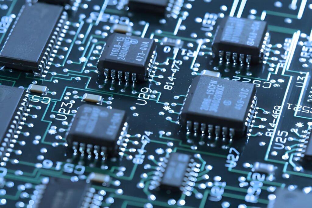
Integrated circuits (ICs) are one of the most critical components in modern printed circuit boards (PCBs) and are widely used in various electronic devices. ICs achieve complex circuit functions by integrating millions of resistors, transistors, and capacitors onto a single micro-sized silicon wafer.
Working Principle
The working principle of integrated circuits is based on semiconductor technology, enabling them to perform a variety of functions, including signal amplification, data processing, and oscillation. Within an integrated circuit, millions of components work together, allowing it to function as an oscillator and amplifier, meeting the demands of different circuits. Through high levels of integration, these ICs can effectively reduce space requirements and enhance overall circuit performance.
Materials and Structure
The basic structure of an integrated circuit includes:
- Silicon Wafer: Serving as the core of the IC, the semiconductor properties of the silicon wafer allow for efficient transmission of electronic signals.
- Packaging: Typically made from plastic or ceramic materials, the packaging protects the internal structure and provides reliable connections.
- Pins: These pins enable the IC to connect with other parts of the circuit board, ensuring signal transmission and power supply.
In PCB manufacturing, integrated circuits are classified into two types: analog and digital. Analog ICs are generally used to process continuous signals, such as audio or video signals, while digital ICs are used for handling discrete signals, suitable for computation, storage, and logical operations. The high integration level and flexibility of integrated circuits make them the preferred choice in modern electronic product design.
Understanding the structure and function of integrated circuits is crucial for circuit design, troubleshooting, and performance optimization. As miniaturization technology continues to advance, integrated circuits will play an increasingly important role in future electronic devices.
Importance and Working Principle of Inductors in Circuit Boards
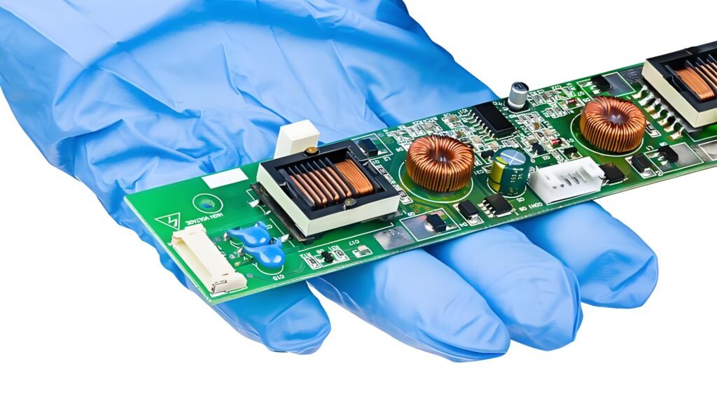
Inductors are a critical type of linear passive component that play an essential role in printed circuit boards (PCBs). As a two-terminal component, the primary function of an inductor is to store energy using a magnetic field and release it to other parts of the circuit when needed.
Working Principle
The working principle of inductors is based on Faraday’s law of electromagnetic induction. When current flows through the inductor’s coil, a magnetic field is generated around it. This magnetic field stores energy, creating the inductive effect. When the current changes, the inductor resists that change, thereby influencing the flow of current. Inductors are commonly used in applications such as filtering, oscillation, and signal coupling.
Materials and Structure
The construction of an inductor generally includes:
- Insulated Coil: The core of the inductor is made from insulated copper wire wound into a coil. The number of turns in the coil directly affects the inductance; more turns result in a stronger magnetic field and greater energy storage.
- Magnetic Core: To enhance the strength of the magnetic field, a magnetic core, typically made from ferrite or silicon steel, is often added to the inductor. The choice of core material significantly impacts the inductor’s performance, improving its efficiency and energy storage capability.
The inductance of an inductor is defined as the ratio of voltage to the rate of change of current over a specified period, usually measured in henries (H). Inductors can be classified into fixed inductors, which have a constant inductance value, and variable inductors, which allow for adjustments based on circuit requirements.
In circuit design, the selection and application of inductors are crucial for the stability and performance of the circuit. Understanding the basic structure, working principle, and role of inductors in various circuits will help engineers better design and optimize electronic devices, ensuring their reliability and efficiency.
The Role and Working Principle of Oscillators in Sub-Devices
Oscillators are indispensable components in sub-devices, functioning similarly to clocks or programmable timers in printed circuit boards (PCBs). Their primary function is to periodically generate stable electronic signals to drive and control various electronic components and circuits.
Working Principle
Oscillators produce waveform signals periodically through specific circuit designs and materials. This process involves the use of piezoelectric materials, which can generate mechanical vibrations when voltage is applied, thus creating the frequency or oscillation of the electrical signal. The output frequency of an oscillator depends on the design of its internal circuitry and the characteristics of the piezoelectric materials used.
Materials and Structure
The most common piezoelectric material used in oscillator manufacturing is quartz crystal. Its advantages include:
- High Stability: Quartz crystals exhibit excellent stability under environmental changes (such as temperature and humidity), making them widely used in applications that require high-precision frequency control.
- Good Frequency Characteristics: Quartz crystals can produce a high Q factor (quality factor), ensuring that the frequency during resonance is very accurate.
The structure of an oscillator typically includes:
- Resonant Cavity: Utilizes the resonant characteristics of quartz crystals to form a cavity that enhances the stability and clarity of the signal.
- Amplifying Circuit: Used to boost the oscillating signal, ensuring that the output signal has sufficient amplitude to drive downstream circuits.
Oscillators come in various types, including sine wave oscillators, square wave oscillators, and clock oscillators, each suited for different application scenarios. In digital circuits, oscillators are commonly used to generate clock signals to synchronize various operations.
Understanding the basic working principles and structure of oscillators will help engineers make more effective choices in circuit design, ensuring that electronic devices achieve optimal performance and stability.
The Function and Application of Switches in Printed Circuit Boards
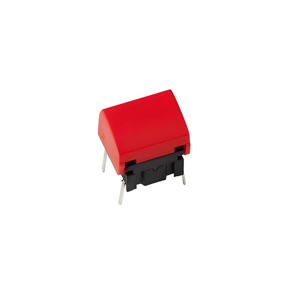
In printed circuit boards (PCBs), switches are one of the fundamental components that play a crucial role. Their primary function is to control the flow of current through simple on/off operations, allowing for effective management and control of the circuit.
Working Principle
When a switch is pressed, it closes the circuit, allowing current to flow freely across the PCB, thereby activating other components and functions. Conversely, when the switch is turned off, it cuts off the current, causing the entire electrical system to cease operation. This process is simple yet vital, ensuring the safe operation and energy efficiency of the device.
Types and Design
There are various types of switches, including:
- Mechanical Switches: Such as push-button switches and toggle switches, suitable for intuitive manual operation.
- Electronic Switches: Such as transistor switches and solid-state switches, capable of achieving faster switching speeds and higher reliability.
- Touch Switches: Activated by touch sensors, commonly found in modern electronic devices.
The design of switches also varies, with common structures including:
- Single Pole Single Throw (SPST): The most basic type of switch, suitable for simple on/off control.
- Double Pole Double Throw (DPDT): Allows for more complex circuit control, enabling multiple function switching.
- Micro Switches: Used in applications requiring small currents or precise control, often found in portable devices.
Materials and Applications
Switches are typically made from durable plastic or metal materials that can withstand frequent operation and environmental pressures. They are widely used in a variety of electronic devices, ranging from simple household appliances to complex industrial control systems, making them ubiquitous.
Understanding the role of switches in circuits and the characteristics of various types will assist engineers in making more appropriate choices when designing PCBs, thereby enhancing overall circuit performance and user experience.
The Role and Types of Potentiometers in Printed Circuit Boards
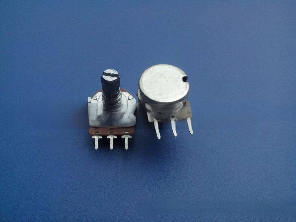
A potentiometer is a variable resistor with three terminals that plays a crucial role in printed circuit boards (PCBs). It is primarily used to adjust voltage or potential, allowing users to flexibly control the flow of current. This makes potentiometers core components in various applications such as volume control and brightness adjustment.
Working Principle
A potentiometer adjusts voltage by changing its resistance value. When a user rotates or slides the control knob or slider of the potentiometer, the resistance changes accordingly, altering the voltage flowing through the circuit. This process enables devices to make precise adjustments based on user needs.
Types
There are mainly two types of potentiometers on the market:
- Linear Potentiometers: These potentiometers have a linear change in resistance, meaning the resistance is proportional to the rotation angle. They are typically used in applications that require smooth, gradual adjustments.
- Rotary Potentiometers: This is a more common type, equipped with a knob that adjusts resistance through rotation. They are widely used in audio equipment and electronic instruments, commonly found in volume control and brightness adjustment functions.
Applications
The flexibility of potentiometers allows them to be used in various devices, including:
- Audio Equipment: For adjusting volume, balance, and sound quality parameters.
- Lighting Control: To adjust light brightness, providing users with a personalized experience.
- Instruments: For setting measurement ranges and calibrating devices.
Materials and Structure
Potentiometers are typically made from carbon film, metal film, or thick film materials to ensure reliability and durability. Their structural design can withstand multiple operations, ensuring stability during long-term use.
Understanding the working principle, types, and applications of potentiometers will help engineers make more appropriate choices in circuit design, thereby enhancing product user experience and performance.
The Application and Function of Silicon Controlled Rectifiers (SCR) in Printed Circuit Boards
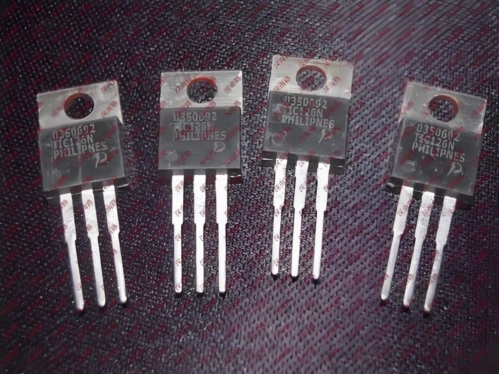
A Silicon Controlled Rectifier (SCR) is a semiconductor device with a four-layer silicon structure, widely used in printed circuit boards (PCBs) to effectively control high current and high voltage. The design of SCRs makes them outstanding for high-power applications, enabling them to perform crucial regulation functions in circuits.
Working Principle
The basic principle of an SCR involves the collaboration of two transistors, controlling the flow of voltage through a trigger signal. When the SCR is in the conducting state, current flows smoothly, while in the off state, the current is blocked. The characteristics of SCRs make them particularly important for power management and high-power control, as they can withstand voltages up to kilovolts.
Application Scenarios
SCRs have a wide range of applications, especially in environments where conventional transistors cannot operate effectively. Some typical application scenarios include:
- Air Conditioning Systems: In air conditioning circuit boards, SCRs are used to control the start and stop of compressors, ensuring stable power supply and preventing overload.
- Motor Control: SCRs can provide precise current control during motor startup and speed adjustment, enhancing system reliability.
- Rectifiers: SCRs are commonly used as rectifying elements in the process of converting alternating current (AC) to direct current (DC), offering efficient energy conversion.
Characteristics and Advantages
The advantages of Silicon Controlled Rectifiers include:
- High Voltage and Current Handling Capacity: SCRs can withstand significant changes in current and voltage, making them suitable for high-power applications.
- Control Flexibility: With a trigger signal, SCRs can respond quickly and provide precise current control.
- Efficiency: SCRs exhibit very low losses during switching operations, resulting in good energy conversion efficiency.
Materials and Structure
SCRs are typically made from high-purity silicon materials, with multiple PN junctions forming their unique four-layer structure. This structure not only enhances their current control capabilities but also improves stability in high-temperature and high-voltage environments.
By understanding the working principle, application scenarios, and technical characteristics of Silicon Controlled Rectifiers, engineers can choose suitable components when designing PCBs, achieving more efficient and reliable power management solutions.
The Importance and Working Principle of Sensors in Circuit Boards

Sensors are indispensable components in printed circuit boards (PCBs), responsible for monitoring and reflecting changes in the surrounding environment. They achieve real-time monitoring and feedback by sensing variations in physical quantities and converting them into electrical signals.
Working Principle
The working principle of sensors is based on the conversion of different physical phenomena. Sensors can detect environmental parameters such as temperature, light intensity, humidity, sound, and motion, and convert these parameters into electrical signals. Specifically, when external conditions change, the sensitive elements within the sensor undergo physical or chemical changes, leading to variations in the electrical signal. These electrical signals are then transmitted to the PCB for processing and analysis.
Materials and Structure
The design of sensors typically includes several key components:
- Sensitive Element: This is the core part of the sensor that directly interacts with the measured physical quantity. The material and design of the sensitive element affect the sensor’s sensitivity and response time. For example, thermistors are used for temperature detection, while photoresistors are used for light intensity monitoring.
- Conversion Mechanism: Sensors usually contain a mechanism for converting physical quantities into electrical signals. This may involve changes in resistance, capacitance, or voltage, depending on the type of sensor.
- Signal Processing Unit: This part is responsible for amplifying, filtering, and converting the electrical signals generated by the sensor to ensure accuracy and reliability.
Sensors play a crucial role in modern electronic devices, enabling real-time monitoring of environmental changes and presenting these changes in a visual manner for easier human understanding and operation. With technological advancements, the variety and application scope of sensors continue to expand, providing strong support for the development of smart devices and automation systems. Understanding the structure and working principle of sensors helps engineers design more precise and efficient monitoring systems.
The Function and Principle of Filters in Circuit Boards
Filters are important signal processing components in circuit boards, primarily used to remove unwanted frequency components, ensuring the purity and stability of signals. They have wide applications in areas such as audio, communication, and power management.
Working Principle
The working principle of a filter is based on selectively transmitting the frequencies of the input signal while suppressing or attenuating specific frequency components. Depending on the design, filters can be categorized as low-pass, high-pass, band-pass, and band-stop filters. Each type of filter has its specific cutoff frequency, beyond which signals will be attenuated.
Materials and Structure
The construction of a filter typically includes the following components:
- Inductor and Capacitor Elements: These components are used to achieve the filtering effect, usually combined in the form of RC, RL, or RLC circuits.
- Enclosure and Packaging: The filter’s enclosure is usually made of plastic or metal to protect the internal components and provide necessary insulation.
- Input and Output Ports: These are used to connect the input and output of the circuit, ensuring smooth signal transmission.
Filters play a crucial role in electronic circuits by eliminating unwanted signal interference, ensuring the normal operation of devices and signal quality. Understanding the basic structure and working principle of filters helps engineers effectively achieve signal processing goals in circuit design.
The Role and Structure of Connectors in Circuit Boards
Connectors are indispensable components in printed circuit boards (PCBs), responsible for establishing connections and signal transmission between circuits. They play a crucial role in electronic devices, enabling efficient and reliable electrical connections between different modules.
Working Principle
The working principle of a connector involves conducting current and signals through metal pins or contact points. When the connector’s plug is inserted into the socket, electrical contact is formed, completing the circuit connection. This connection is typically designed to be plug-and-play, allowing for maintenance or replacement when needed.
Materials and Structure
The main structure of a connector includes:
- Plug and Socket: The plug typically contains multiple metal pins, while the socket has corresponding contact points. These components make contact when inserted, forming the circuit connection.
- Housing: The connector housing is usually made from plastic or metal materials, providing physical protection and insulation to prevent external environmental factors from affecting electrical contacts.
- Locking Mechanism: Some connectors are equipped with locking mechanisms to ensure that the connection is secure and does not easily disconnect, enhancing reliability.
Connectors are essential in circuit boards, ensuring stable electrical connections and signal transmission between different modules. Understanding the structure and working principle of connectors can help engineers choose appropriate connection solutions in their designs, improving system reliability.
The Best Ways to Purchase PCB Components
When searching for PCB components, you can visit local hardware and electronics stores, which typically stock a variety of common electronic components for immediate purchase. Additionally, many well-known online stores offer a wide selection of PCB components, allowing you to easily browse and compare prices to find products that best suit your needs.
For projects requiring special or custom components, CustomPCBA provides a one-stop service. We not only help you source various PCB components but also offer customization based on your specific requirements. Our experienced team can provide professional advice and support to ensure your project runs smoothly.
If you have any questions or need further information, please feel free to contact us, and we will be happy to assist you.
