
Wondering how to fix a PCBA board? A failure doesn’t always mean full replacement—sometimes, simple diagnostics and repair steps can restore the board to full functionality.
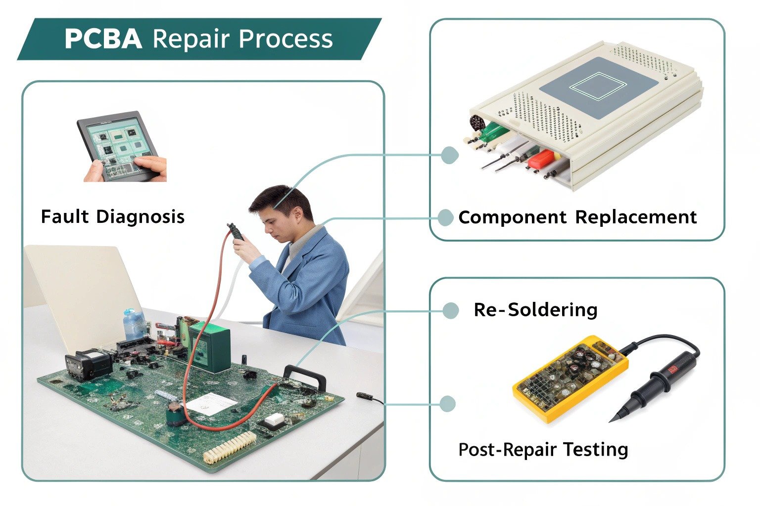
Fixing a PCBA board involves diagnosing faults, replacing or re-soldering components, and testing the board to restore its function. With the right tools and care, many PCBAs can be repaired.
When a PCBA (Printed Circuit Board Assembly) stops working, it’s easy to assume it’s beyond saving. But in many cases, the issue is minor—a broken trace, a cold solder joint, or a faulty capacitor. Whether you’re repairing prototypes, products in warranty, or debugging during development, knowing how to fix a PCBA board is a valuable skill.
In this guide, I’ll walk you through how to identify common faults, what tools you need, and how to safely carry out repairs without making things worse.
What Causes PCBA Boards to Fail?
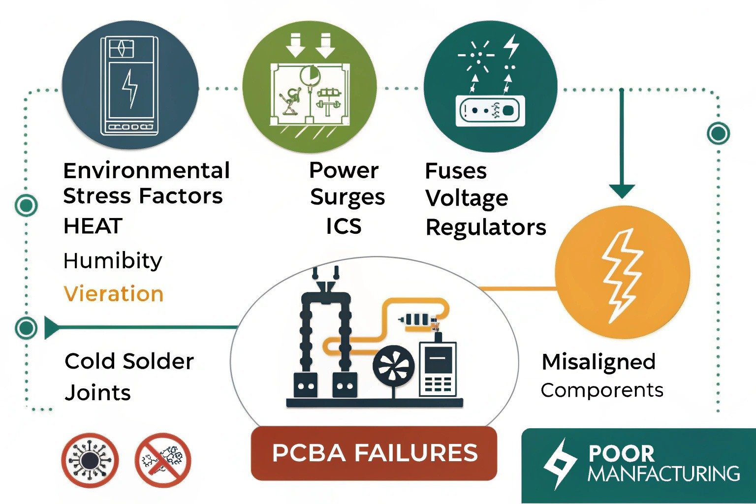
Before jumping into repair, it’s important to understand what went wrong. PCBA failures can come from various sources:
Environmental stress—like heat, humidity, or vibration—can weaken solder joints or crack fragile components. Power surges can blow out ICs, fuses, or voltage regulators. Poor manufacturing may result in cold solder joints, misaligned parts, or even missing components.
The most common causes of PCBA failure include:
- Broken or lifted traces due to mechanical pressure or burns
- Failed capacitors or resistors, especially if they show burn marks or discoloration
- Faulty solder joints, which may crack or loosen over time
- ESD damage, especially on sensitive microcontrollers or logic ICs
Visual inspection is often the first step in identifying these problems. Under a magnifier or microscope, burned spots, loose pins, or corroded pads become much easier to spot.
Tools You Need for PCBA Repair
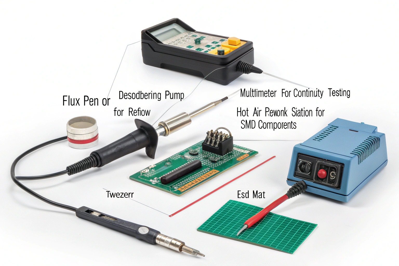
You don’t need a high-end lab to fix most PCBAs, but you do need the right tools. Here’s a short list of essentials:
- Soldering iron with temperature control
- Desoldering pump or braid for component removal
- Multimeter for checking continuity and voltage
- Hot air rework station (for SMD components)
- Flux pen or paste to improve solder quality
- Tweezers, magnifier, and ESD mat for safe handling
Having access to a schematic or layout file helps speed up diagnostics. If you don’t have one, tracing connections manually is still possible—but takes more time.
For more on tools, see this repair station setup guide by Adafruit.
Steps to Fix a Faulty PCBA Board
Once you’ve identified a suspect component or area, follow this general process to fix the board safely:
Step 1: Visual Inspection
Use good lighting and a magnifier to check for cracked components, lifted pads, or burnt areas. Look for cold solder joints—these appear dull, cracked, or blob-like instead of shiny and smooth.
Step 2: Test with a Multimeter
Use the continuity mode to check if traces are broken or if a short circuit is present. Measure voltages at power rails or IC pins to see if expected values are present.
Step 3: Remove the Faulty Component
Use a soldering iron and wick or a hot air station to desolder the damaged part. Be gentle—lifting pads can permanently damage the board.
Step 4: Clean the Pads and Apply Flux
After removing the component, clean the area with isopropyl alcohol. Apply flux to prepare the pads for the new solder joint.
Step 5: Solder the Replacement Component
Carefully place the new part using tweezers. Use the right amount of solder and minimal heat to avoid thermal damage. Reflow the joint with smooth, shiny finishes.
Step 6: Test Again
Once replaced, test the circuit. Power it up (safely!) and check if voltages are stable and the function has returned. If possible, run the board through the original test program or firmware routine.
This process works for both through-hole and SMD components, but handling SMDs requires more precision due to their size and spacing.
When Repair Isn’t the Best Option
Not every PCBA can or should be repaired.
If the board is multilayered and the fault lies inside an internal trace or via, repair may be impossible without specialized tools. Similarly, if the board has suffered extensive damage from power surges, fire, or water corrosion, replacing it may be more cost-effective.
Other times, labor costs exceed the board’s value. In these cases, reworking isn’t worth it, especially for mass-produced, low-cost devices like toys or remote controls.
In mission-critical or certified products (e.g. medical, aerospace), even if a repair is possible, it might violate compliance standards, making replacement the only legal choice.
Conclusion
Fixing a PCBA board isn’t magic—it’s a matter of careful inspection, methodical testing, and precise repair. With basic tools and a steady hand, you can bring many faulty boards back to life and avoid unnecessary replacements.
Whether you’re debugging prototypes or repairing commercial devices, learning how to fix a PCBA board adds huge value to your skillset and can save time, cost, and frustration.
